Ten steps to a Windows Server 2003 virtual cluster configuration
Configure and test a Windows Server 2003 cluster on your desktop using virtualization technology with these ten easy steps.
Is your company considering a high-availability solution or disaster recovery plan for Exchange, SQL Server, Internet Information Services or a third-party offering? Take advantage of desktop virtualization to configure and test an HA plan on a desktop or laptop computer, saving your company thousands of dollars.
This tutorial demonstrates 10 easy steps to configuring and simulating a Windows Server 2003 cluster on your desktop using VMware Workstation.
You will need a trial or licensed version of VMware Workstation. Download a trial copy of VMware Workstation, follow the wizard, install VMware Workstation and reboot. After completing the following steps, you will have successfully configured a virtual cluster.
Step 1: Create a virtual environment
The first step is to prepare the virtual environment to work with clustering. to create a clustering solution, you will need to do the following:
- Create, install and configure a virtual Windows 2000 or Windows 2003 domain controller with domain name server (DNS) installed and configured. When creating Windows 2003 virtual machines, accept the default of LSI Logic Adapter in the New Virtual Machine wizard.
- Create, install and configure two VMs with Windows 2000 Advanced Server or Windows 2003 Server Enterprise Edition.
- Ensure that any VM participating in the cluster has a public and private network configuration. Each node will need two network cards -- each with a public IP address and a private IP address.
- Ensure that all of these virtual servers have static IP addresses.
- Ensure that VMs that are going to represent the nodes of the cluster are joined to the domain.
- Have access to the Windows 2000 Advanced Server CD-ROM or copy the I386 directory to the VM.
- Have access to the Windows 2003 Enterprise Edition CD-ROM or copy the I386 directory to the VM.
- Create a domain user account on the domain controller, such as Cluster_Service. This account will be used to run the cluster service.
Once you have the environment configured, the next step is to add additional network cards to the nodes that will participate in the cluster.
Add network cards to the cluster nodes
Once you have created the disks, you also need to run the hardware wizard and add a second Ethernet adapter to each virtual machine that will be participating in the cluster.
- Highlight the applicable virtual machine and edit the virtual machine settings.
- Click Add on the hardware tab.
- Select Ethernet Adapter.
- Click Finish to add the adapter.
The VMware Control Center will display the additional network card as shown in Figure 1.
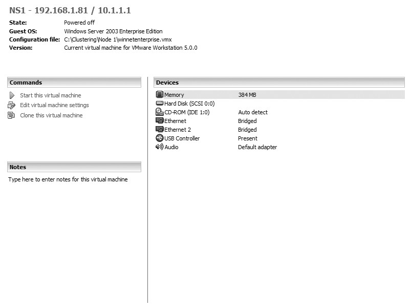
Figure 1 VMware Control Center displaying the additional network card. (Click on image for enlarged view.)
| Note: For the purpose of this example, we are using a bridged network connection for all Ethernet Adapters. |
Step 2: Create a private network configuration
For clustering to work properly, you must configure two network cards on each VMware Workstation virtual server. The private network allows for communication between each of the nodes, commonly known as the heartbeat. Follow these instructions to add a network card:
- Open VMware Workstation from the start menu.
- Select Settings from the VM menu.
- Choose Add and select Network Adapter.
- Click Next and select Bridged Connection.
- Click Finish.
The next time you power on the virtual server, it will have an additional network card. Repeat these steps on each VM that will be part of the cluster.
(For example, assume that you have two VMs [swcluster1 and swcluster2]. Once additional network cards have been added, you will have to configure them for the heartbeat connection. You might configure your heartbeat on node 1 [swcluster1] with the IP address 10.1.1.2, and on node 2 [swcluster2] with the IP address 10.1.1.3. )
When you set up the static IP address, it is important that you select the Advanced tab in the TCP/IP properties dialog box and choose Disable NetBIOS over TCP/IP, as shown in Figure 2. All cluster nodes communicate via TCP/IP only. If you do not choose this option, problems may occur with node-to-node communication.
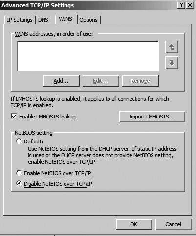
Figure 2 Choose Disable NetBIOS over TCP/IP in the Advanced tab. (Click on image for enlarged view.)
Step 3: Configure a public network connection
To configure your public network connection, right-click on your second network card and assign the appropriate IP address, DNS and WINS settings. To verify connectivity, open a command prompt and type < code>ipconfig /all (as shown in Figure 3) on each node in the cluster to verify the configurations. When each node is properly configured with a private and a public network address and connectivity has been tested, the next step is to make sure that each node is connected to the domain.
- Right-click on My Computer.
- Click on the Network Identification tab (on both clustered machines).
- Verify that you are connected to the desired Active Directory domain.
- Power down both nodes, leaving the domain controller running.
Before you begin to install clustering, you must know your virtual server's name and the IP address you are assigning to the cluster.
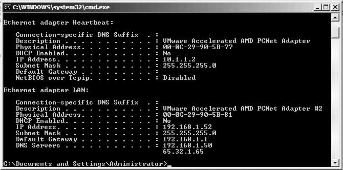
Figure 3 Verifying connectivity. (Click on image for enlarged view.)
Step 4: Configure shared disks in VMware Workstation
To configure your shared disks, create a folder on your hard drive and label it accordingly. For this example, we will call the folder Cluster_Disks, as shown in Figure 4.
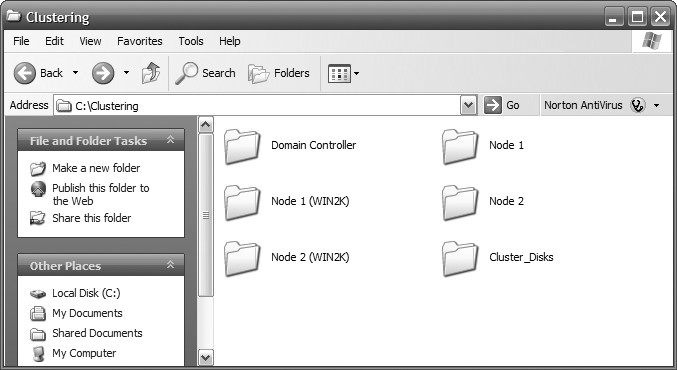
Figure 4 Create a folder on your hard drive and label accordingly. (Click on image for enlarged view.)
Next, highlight any one of the three VMs you created in the favorites window and edit virtual machine settings. In the Virtual Machine Settings window, click Add to start the Add Hardware Wizard and do the following:
- Choose Hard Disk on the Hardware Type window.
- Click Next.
- On the Select a Disk window, choose Create a new virtual disk.
- Click Next.
- On the Select a Disk Type window, accept the default of SCSI (recommended).
- Click Next.
The Specify Disk Capacity screen is where you will size the virtual disk. Make sure to size this according to your needs. When you have finished sizing the disk accordingly, select the Allocate all disk space now checkbox as shown in Figure 5.
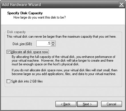
Figure 5 Select "Allocate all disk space now". (Click on image for enlarged view.)
Click Next and view the folder where your shared disks will be stored (Figure 6). Click Finish to create the shared disk. Depending on the size of the disk, this can take a while to create (Figure 7).
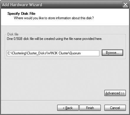
Figure 6 Browse to the folder where your shared disks are stored. (Click on image for enlarged view.)

Figure 7 Shared disc creation may take some time. (Click on image for enlarged view.)
After the disk has been created, highlight the disk on the Hardware tab and click Remove, as shown in Figure 8. The first disk we created was the quorum disk. Next, we will create two more shared disks. This will allow for a configuration of an active/passive cluster or an active/active cluster. Repeat the process to create two additional shared disks.
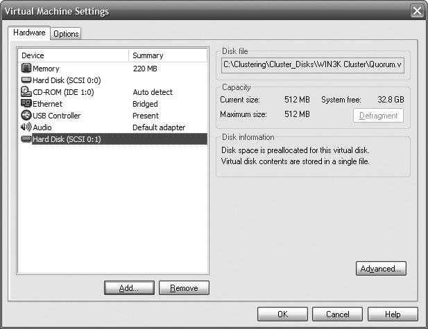
Figure 8 Highlight the disc on the hardware tab. (Click on image for enlarged view.)
| Note: It is very important to remove the disk from the Hardware tab after it is configured. Do not forget to do this. Highlight each disk you created and click the Remove button. |
After you've created your disks, the disk configuration is displayed in the Cluster_Disks folder (Figure 9).
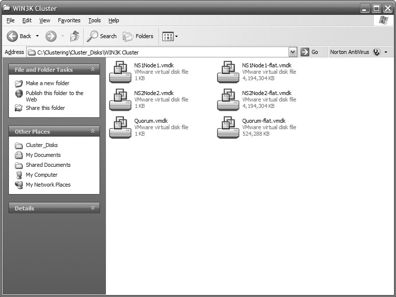
Figure 9 Disk configuration. (Click on image for enlarged view.)
Step 5: Edit the VMX file for each cluster node
Now that the shared disks have been created, the VMX or VMware Configuration file must be modified for each node that will participate in the cluster. To edit the *.vmx file, browse to the location of your VMs and open the file (.vmx) in Notepad. Figure 10 illustrates how to open a *.vmx file in Notepad.
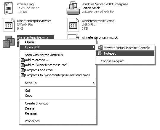
Figure 10 How to open a *.vmx file in Notepad. (Click on image for enlarged view.)
| Note: Do not attempt this step if your VMs are running. Make sure they are powered off and that you have EXITED from the VMware Workstation program. Once you have exited the program, follow these steps. If you do not exit VMware Workstation, the shared disks will not boot properly and you will have to boot into the BIOS to correct the problem. |
After opening the *.vmx file in Notepad for the applicable VM, add the following lines to the VMware Configuration file:
disk.locking="false"
scsi1:0.present="TRUE"
scsi1:0.filename="path to vmdk file"
scsi1:0.mode="independent-persistent"
scsi1:1.present="TRUE"
scsi1:1.filename="path to vmdk file"
scsi1:1.mode="independent-persistent"
By adding the disk.locking="false", you allow the disk to be shared. Scsi1:0.filename is the location of your shared disk. Setting the disk to independent persistent safeguards the shared disk, as information is permanently written to the disk and is not affected by snapshots. For every disk you use, you must increase the number. Refer to this example:
SCSI1:0 will be the Quorum drive, SCSI1:1 will be another disk and SCSI1:2 will be the second disk. Therefore, you would add the following code to your configuration:
disk.locking="false"
scsi1:0.fileName = "C:ClusteringCluster_DisksWIN3K
ClusterQuorum.vmdk"
scsi1:0.mode = "independent-persistent"
scsi1:1.present = "TRUE"
scsi1:1.fileName = "C:ClusteringCluster_DisksWIN3K
ClusterNS1Node1.vmdk"
scsi1:1.mode = "independent-persistent"
scsi1:2.present = "TRUE"
scsi1:2.fileName = "C:ClusteringCluster_DisksWIN3K
ClusterNS2Node2.vmdk"
scsi1:2.mode = "independent-persistent"
Make sure that both VMs have *.vmx files updated with the appropriate syntax. Refer to figure 11 and figure 12, illustrate the *.vmx file on both VMs.
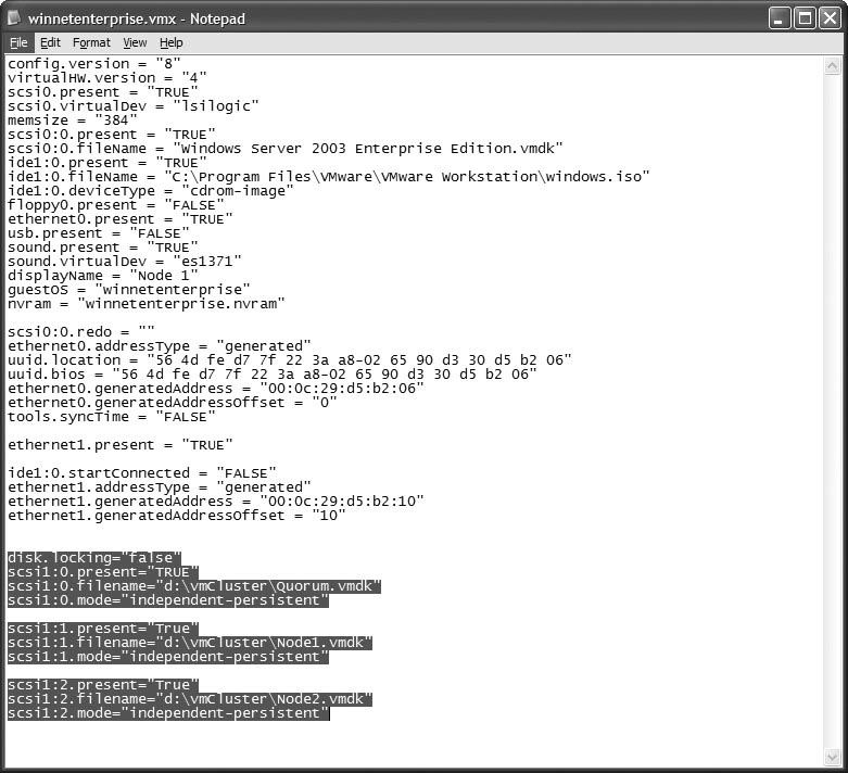
Figure 11 Illustrates the *.vmx file on one of the virtual machines. (Click on image for enlarged view.)
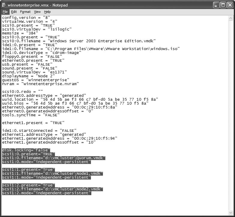
Figure 12 Illustrates the *.vmx file on one of the virtual machines. (Click on image for enlarged view.)
After the information is added to the virtual machine configuration files, the VMware Control Center will show you the new disk configuration and the disks will appear in the lower right-hand corner. Figure 13 and figure 14 illustrate the disk configuration and the virtual disks in action, respectively.
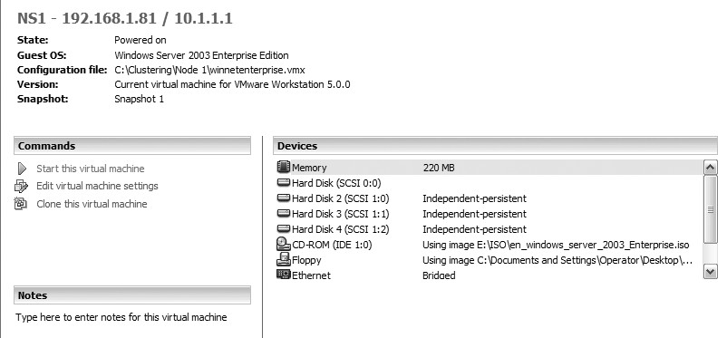
Figure 13 Illustrates the disk configuration. (Click on image for enlarged view.)

Figure 14 The virtual discs in action. (Click on image for enlarged view.)
Now you're ready to power on the first VM in the cluster. Don't activate both VMs at the same time. Power on the first one, configure the disks and install the cluster service before turning on the second VM.
Step 7: Boot into the BIOS
If you power on your virtual machine for the first time and it tries to boot from a shared disk, you must turn each node to the basic input/output system (BIOS) to make sure the disks will load in the appropriate order. Power on the first computer and follow these steps:
- Choose F2 to enter the BIOS.
- Use the arrow keys to move to the boot menu.
- On the boot menu, move the arrows until the focus is on the hard drive.
- Hit Enter and make sure Disk (0:0) is at the beginning of the boot order.
When you configure a cluster, the boot disk goes last, so if you do not perform these steps you won't be able to boot your OS after adding the shared disks. Once you have Disk (0:0) at the beginning of the boot order, save your changes and repeat the process on the second node.
Step 8: Configure the drives on the virtual machine
Once you've successfully added the shared disks, you can power up the first VM. To configure your drives, follow these steps:
- Right-click on My Computer.
- Select Manage. (This can also be accessed through Administrative Tools.)
- Under Storage, select Disk Management to open the Computer Management Console.
- When you go into Disk Management for the first time, you will be prompted to write the disk signature and upgrade the disk to a dynamic disk.
- Choose Yes to write the disk signature; choose No when asked if you'd like to upgrade the disk to a dynamic disk.
| Note: If you accidentally upgrade the disks to dynamic disks, don't worry -- you can simply right-click on the Disk box and choose Revert to Basic. |
Clustering must contain basic disks to work properly. Verify that you can see the unformatted shared disks (Figure 15) via Disk Management. Once you've verified that you can see the shared disk, you can partition the disk accordingly. In this example, the nodes are being prepared for an active/active cluster of SQL Server 2000 and SQL Server 2005. The following will be the disk configuration:
- Disk 1 will be the Quorum drive.
- Disk 2 will be the first instance data and log drive.
- Disk 3 will be the second instance data and log drive.
Figure 16 shows this disk configuration when it is complete.
| Note: We could have added two more drives as well to separate SQL Server's data and log drives. |
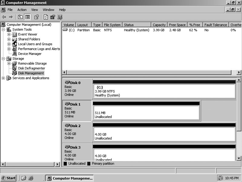
Figure 15 Can you see the unformatted shared disks via Disk Management? (Click on image for enlarged view.)
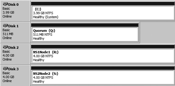
Figure 16 The completed disc configuration. (Click on image for enlarged view.)
Step 9: Configure the cluster service on a Windows Server 2003
We are finally at the testing phase; this is the easy part. Start by clicking Start → All Programs → Administrative Tools → Cluster Administrator. The Cluster Administrator window will appear with an Open Connection to Cluster dialog box. Click the drop down menu and choose Create new cluster, as shown in Figure 17.
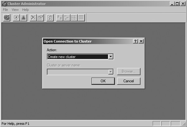
Figure 17 What you will see in the Cluster Administrator window. (Click on image for enlarged view.)
In the New Server Cluster Wizard, choose a valid cluster name and click Next to continue, as shown in Figure 18. After a valid cluster name has been entered, the computer name of the node participating in the cluster is populated (Figure 19).
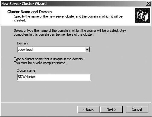
Figure 18 New Server Cluster Wizard. (Click on image for enlarged view.)
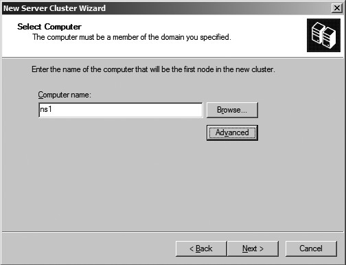
Figure 19 The computer name of the node participating in the cluster is populated. (Click on image for enlarged view.)
When the Analyzing Configuration window is open (Figure 20), the wizard does the following:
- Checks for existing cluster
- Establishes node connection(s)
- Checks node feasibility
- Finds common resources on nodes
- Checks cluster feasibility
You can expand the "+" signs to make sure everything looks acceptable in your cluster, as shown in Figure 21. Additionally, you can view the log and details by selecting the appropriate button. If your cluster has problems, fix them as defined in the configuration and reanalyze.

Figure 20 The Analyzing Configuration window. (Click on image for enlarged view.)

Figure 21 Expand the + signs to make sure everything in your cluster looks good. (Click on image for enlarged view.)
In the IP address window, enter the cluster IP address as shown in Figure 22. This will be the IP address to manage the cluster. While in the Cluster Service Account window, enter a valid domain user account that the cluster service will use (Figure 23). This account will be added to the local administrator group on all nodes of the cluster.
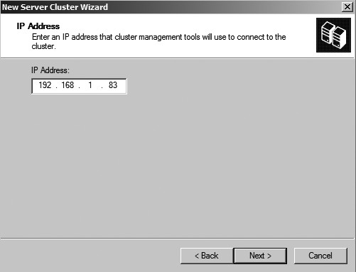
Figure 22 Input the cluster IP address. (Click on image for enlarged view.)
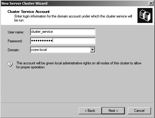
Figure 23 The Cluster Service Account window. (Click on image for enlarged view.)
The Proposed Cluster Configuration window (Figure 24) allows you to review your configuration and make changes if necessary. Click on the Quorum button to make sure the right disks have been assigned (Figure 25) to the quorum. Click Next to create the cluster configuration.
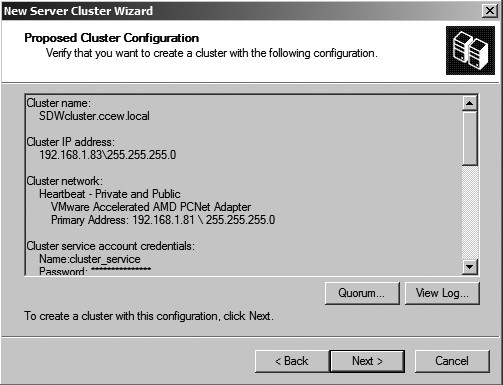
Figure 24 The Proposed Cluster Configuration window. (Click on image for enlarged view.)
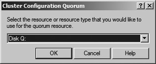
Figure 25 Click on the Quorum button to make sure the right disk have been assigned to the quorum. (Click on image for enlarged view.)
Once the cluster configuration process is complete, you can review the details by expanding the "+" signs. Figure 26 illustrates a completed cluster configuration. Click Next and Finish and you have successfully configured your first virtual node with a Windows 2003 cluster. The next step is to power on the second node.
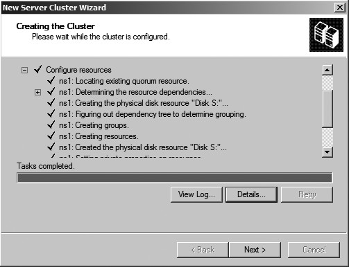
Figure 26 Completed cluster configuration. (Click on image for enlarged view.)
Click Start → All Programs → Administrative Tools → Cluster Administrator and the Cluster Administrator window will appear with an Open Connection to Cluster dialog box. Click the drop down menu and choose Add nodes to cluster and the cluster name, as shown in Figure 27. Click OK and the Welcome to the Add Nodes Wizard appears.
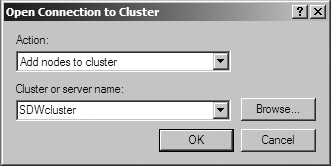
Figure 27 The Open Connection to Cluster window. (Click on image for enlarged view.)
The computer name automatically populates the Computer Name text box in the Select Computer window. Click Add to add the computer to the list, as shown in Figure 28. The configuration is analyzed and, if there are no problems, you can continue to enter the Cluster Service Account window in the wizard, as shown in Figure 29.
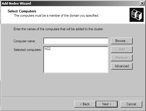
Figure 28 Select computers window. (Click on image for enlarged view.)

Figure 29 The Cluster Service Account window. (Click on image for enlarged view.)
You will now be asked to review the configuration. Click Next and the node will be added to the cluster. Finally, click Finish. A virtual Windows 2003 cluster has now been successfully created.
Step 10: Test the Windows 2003 Cluster
To test the failover process, right click on any group and choose Move group (Figure 30). If everything is configured properly, the group will move from its current node to the available node. Another test would be to move all of the groups to a particular node and then power off the VM that is currently active. You can actually see the failover occur. This would simulate a total shutdown or failure of a node. To simulate a failover:
- Expand the Groups folder.
- Highlight a group in the details pane.
- Right-click on the disk.
- Choose Initiate Failure (Figure 31).
You will see some minor activity and then the status will return to normal. This happens because the cluster will try to correct itself three times before failing over. You must initiate a failure four times in a row to have the disk move nodes.
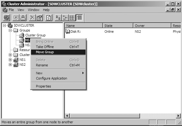
Figure 30 Test the failover process by right-clicking on any group. (Click on image for enlarged view.)
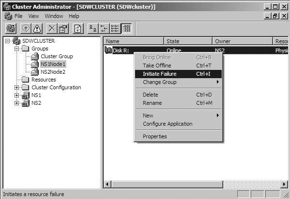
Figure 31 Simulate a failover. (Click on image for enlarged view.)
Congratulations on configuring a virtual cluster. I suggest that you play around and have fun with it. At this point you can load SQL Server 2008 or Exchange Server and begin testing directly from the desktop.
ABOUT THE AUTHOR:
Steve S. Warren is a freelance writer with a passion for learning. He is the author of The VMware Workstation 5 Handbook and is a Microsoft MVP. When he is not writing, he is spending time with his family and friends. You can also find him on Twitter and LinkedIn.