Using Microsoft Cluster Services for virtual machine clustering
Microsoft Cluster Services are useful for the different virtual machine (VM) clustering scenarios that are available, such as cluster in a box, and help with cluster node creation.
Solutions provider takeaway: There are a few different scenarios involved when using Microsoft Cluster Services for Windows Server virtual machine (VM) clustering. This Chapter excerpt will delve into cluster in a box and cluster across boxes, how to create cluster nodes and physical to virtual clustering.
|
||||
After all your servers are installed, all storage is provisioned, all virtual networking is pinging, and all virtual machines are running, it is time to define the strategies or the methods to put into place in a virtual infrastructure that will provide high availability and business continuity. The deployment of a virtual infrastructure opens many new doors for disaster-recovery planning. The virtual infrastructure administrator will lead the charge into a new era of ideologies and methodologies for ensuring that business continues as efficiently as possible in the face of corrupted data, failed servers, or even lost datacenters.
With the release of VMware vSphere, we have been given more tools at our disposal to reach our goal of increased uptime and recoverability of the infrastructure. You'll learn about the methods and new features available to reach this goal.
In this chapter, you will learn to:
- Understand Windows clustering and the types of clusters
- Understand built-in high availability options
- Understand the differences between VCB and VCDR
- Understand data replication options
Clustering Virtual Machines
Let's start with the most well-known technique for helping administrators achieve high availability: Microsoft Clustering Service (MSCS), or failover clustering as it is called in Windows 2008. Failover clustering in Windows 2008 is used when critical services and applications call for the highest levels of availability. Microsoft Windows Server 2003 and 2008 both support network load balancing (NLB) clusters as well as server clusters depending on the version of the Windows Server operating system that is installed on the server. Moving forward, I'll just use the term Microsoft Clustering Service or MSCS to describe any forms or versions of Windows clustering.
Microsoft Clustering
The NLB configuration involves an aggregation of servers that balances the requests for applications or services. In a typical NLB cluster, all nodes are active participants in the cluster and are consistently responding to requests for services. NLB clusters are most commonly deployed as a means of providing enhanced performance and availability. NLB clusters are best suited for scenarios involving Internet Information Services (IIS), virtual private networking (VPN), and Internet Security and Acceleration (ISA) server, to name a few. Figure 11.1 details the architecture of an NLB cluster.
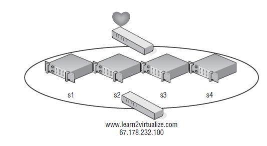
Figure 11.1
An NLB cluster can contain up to 32 active nodes that distribute traffic equally across each node. The NLB software allows the nodes to share a common name and IP address that is referenced by clients.
NLB Support from VMware
As of this writing, VMware supports NLB, but you will need to run NLB in multicast mode to support VMotion and virtual machines on different physical hosts. You will also need to configure static address resolution protocol (ARP) entries on the physical switch to achieve this. If NLB is running in unicast mode, then the virtual machines will all need to be running on the same host. Another option to consider would be the use of third-party load balancers to achieve the same results.
Unlike NLB clusters, server clusters are used solely for the sake of availability. Server clusters do not provide performance enhancements outside of high availability. In a typical server cluster, multiple nodes are configured to be able to own a service or application resource, but only one node owns the resource at a given time. Server clusters are most often used for applications like Microsoft Exchange, Microsoft SQL Server, and DHCP services, which each share a need for a common datastore. The common datastore houses the information accessible by the node that is online and currently owns the resource, as well as the other possible owners that could assume ownership in the event of failure. Each node requires at least two network connections: one for the production network and one for the cluster service heartbeat between nodes. Figure 11.2 details the structure of a server cluster.
The different versions of Windows Server 2003 and 2008 offer various levels of support for NLB and server clusters. Table 11.1 outlines the cluster support available in each version of Windows Server 2003. The only difference in Windows 2008 is that a server cluster can have up to 16 nodes.
Table 11.1: Windows Server 2003 Clustering Support
|
|
|
|
| Windows Server 2003/2008 Web Edition | Yes (up to 32 nodes) | No |
| Windows Server 2003/2008 Standard Edition | Yes (up to 32 nodes) | No |
| Windows Server 2003/2008 Enterprise Edition | Yes (up to 32 nodes) | Yes (up to 8 nodes in 2003 and 16 nodes in 2008) |
| Windows Server 2003/2008 Datacenter Edition | Yes (up to 32 nodes) | Yes (up to 8 nodes in 2003 and 16 nodes in 2008) |
Windows Clustering Storage Architectures
Server clusters built on Windows Server 2003 can support only up to eight nodes, and Windows 2008 can support up to 16 nodes when using a Fibre Channel–switched fabric. Storage architectures that use SCSI disks as direct attached storage or that use a Fibre Channel–arbitrated loop result in a maximum of only two nodes in a server cluster. Clustering virtual machines in an ESX/ESXi host utilizes a simulated SCSI shared storage connection and is therefore limited to only two-node clustering. In addition, in ESX 3.x, the clustered virtual machine solution uses only SCSI 2 reservations, not SCSI 3 reservations, and supports only the SCSI miniport drivers, not the Storport drivers. This has been changed in VMware vSphere, which now allows SCSI 3 reservations and the use of the Storport drivers.
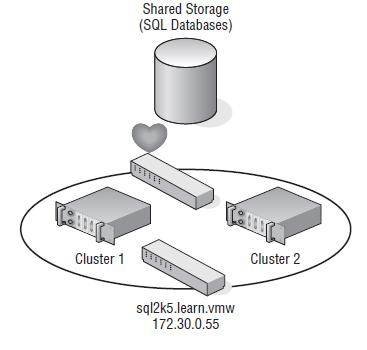
Figure 11.2
Server clusters are best suited for applications and services like SQL Server, Exchange Server, DHCP, and so on, that use a common data set.
MSCS, when constructed properly, provides automatic failover of services and applications hosted across multiple cluster nodes. When multiple nodes are configured as a cluster for a service or application resource, as I said previously, only one node owns the resource at any given time. When the current resource owner experiences failure, causing a loss in the heartbeat between the cluster nodes, another node assumes ownership of the resource to allow continued access with minimal data loss. To configure multiple Windows Server nodes into a Microsoft cluster, the following requirements must be met:
- Nodes must be running either Windows Server Enterprise Edition or Datacenter Edition
- All nodes should have access to the same storage device(s)
- All nodes should have two similarly connected and configured network adapters: one for the production network and one for the heartbeat network
- All nodes should have Microsoft Cluster Services for the version of Windows that you are Using
Virtual Machine Clustering Scenarios
The clustering of Windows Server virtual machines using Microsoft Cluster Services can be done in one of three different configurations. The following gives you a quick peek now, and I will get into more details in a minute:
Cluster in a box The clustering of two virtual machines on the same ESX/ESXi host is also known as a cluster in a box. This is the easiest of the three configurations to set up. No special configuration needs to be applied to make this configuration work.
Cluster across boxes The clustering of two virtual machines that are running on different ESX/ESXi hosts is known as a cluster across boxes. VMware had restrictions in place for this configuration in earlier versions: the cluster node's C: drive must be stored on the host's local storage or local VMFS datastore, the cluster shared storage must be stored on Fibre Channel external disks, and you must use raw device mappings on the storage. This has been changed and updated to allow .vmdk files on the SAN and to allow the cluster VMboot drive or C: drive on the SAN, but VMotion and Distributed Resource Scheduling (DRS) are not supported using Microsoft-clustered virtual machines. The exact warning from VMware is ''Clustered virtual machines cannot be part of VMware clusters (DRS or HA).''
Physical to virtual clustering The clustering of a physical server and a virtual machine together is often referred as a physical to virtual cluster. This configuration of using both physical and virtual servers together gives you the best of both worlds, and the only other added restriction is that you cannot use virtual compatibility mode with the RDMs. I'll cover these options in more detail and show how to set them up in a virtual environment later in this chapter.
Clustering has long been considered an advanced technology implemented only by those with high technical skills in implementing and managing high-availability environments. Although this might be more rumor than truth, it is certainly a more complex solution to set up and maintain.
Although you might achieve results setting up clustered virtual machines, you may not receive support for your clustered solution if you violate any of the clustering restrictions put forth by VMware. The following list summarizes and reviews the do's and don'ts of clustering virtual machines as published by VMware:
- 32-bit and 64-bit virtual machines can be configured as nodes in a server cluster.
- Majority Node Set clusters with application-level replication (for example, Microsoft Exchange 2007 Cluster Continuous Replication) is now supported.
- Only two-node clustering is allowed.
- Clustering is not supported on iSCSI or NFS disks.
- Clustering does not support NIC teaming in the virtual machines.
- Virtual machines configured as cluster nodes must use the LSI Logic SCSI adapter and the vmxnet network adapter.
- Virtual machines in a clustered configuration are not valid candidates for VMotion, and they can't be part of a DRS or HA cluster.
- ESX/ESXi hosts that run virtual machines that are part of a server cluster can now be configured to perform a boot from SAN.
- ESX/ESXi hosts that run virtual machines that are part of a server cluster cannot have both QLogic and Emulex HBAs.
There is something else that you need to do. You must set the I/O timeout to 60 seconds or more by modifying HKLM\System\CurrentControlSet\Services\Disk\TimeOutValue, and if you re-create a cluster, you need to reset the value again.
So, let's get into some more details on clustering and look at the specific clustering options available in the virtual environment. I will start with the most basic design configuration, the cluster in a box.
Examining Cluster-in-a-Box Scenarios
The cluster-in-a-box scenario involves configuring two virtual machines hosted by the same ESX/ESXi host as nodes in a server cluster. The shared disks of the server cluster can exist as .vmdk files stored on local VMFS volumes or on a shared VMFS volume. Figure 11.3 details the configuration of a cluster in a box.
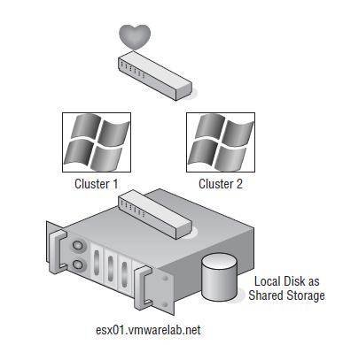
Figure 11.3
A cluster-in-a-box configuration does not provide protection against a single point of failure. Therefore, it is not a common or suggested form of deploying Microsoft server clusters in virtual machines.
After reviewing the diagram of a cluster-in-a-box configuration, you might wonder why you would want to deploy such a thing. The truth is, you wouldn't want to deploy cluster-in-a-box configuration because it still maintains a single point of failure. With both virtual machines running on the same host, if that host fails, both virtual machines fail. This architecture contradicts the very reason for creating failover clusters. A cluster-in-a-box configuration still contains a single point of failure that can result in downtime of the clustered application. If the ESX/ESXi host hosting the two-node cluster-in-a-box configuration fails, then both nodes are lost, and a failover does not occur. This setup might, and I use might loosely, be used only to ''play'' with clustering services or to test clustering services and configurations. But ultimately, even for testing, it is best to use the cluster-across-box configurations to get a better understanding of how this might be deployed in a production scenario.
Configuration Options for Virtual Clustering
As suggested in the first part of this chapter, server clusters are deployed for high availability. High availability is not achieved by using a cluster-in-a-box configuration, and therefore this configuration should be avoided for any type of critical production applications and services.
Examining Cluster-Across-Boxes Configurations
Although the cluster-in-a-box scenario is more of an experimental or education tool for clustering, the cluster-across-boxes configuration provides a solid solution for critical virtual machines with stringent uptime requirements—for example, the enterprise-level servers and services like SQL Server and Exchange Server that are heavily relied on by the bulk of end users. The cluster-across-boxes scenario, as the name applies, draws its high availability from the fact that the two nodes in the cluster are managed on different ESX/ESXi hosts. In the event that one of the hosts fails, the second node of the cluster will assume ownership of the cluster group, and its resources and the service or application will continue responding to client requests.
The cluster-across-boxes configuration requires that virtual machines have access to the same shared storage, which must reside on a Fibre Channel storage device external to the ESX/ESXi hosts where the virtual machines run. The virtual hard drives that make up the operating system volume of the cluster nodes can be a standard VMDK implementation; however, the drives used as the shared storage must be set up as a special kind of drive called a raw device mapping (RDM). An RDM is a feature that allows a virtual machine to establish direct access to a LUN on a SAN device.
Using Raw Device Mappings in your Virtual Clusters
An RDM is not a direct access to a LUN, and it is not a normal virtual hard disk file. An RDM is a blend between the two. When adding a new disk to a virtual machine, as you will soon see, the Add Hardware Wizard presents the RDMs as an option on the Select a Disk page. This page defines the RDM as having the ability to give a virtual machine direct access to the SAN, thereby allowing SAN management. I know this seems like a contradiction to the opening statement of this sidebar; however, I'm getting to the part that, oddly enough, makes both statements true.
By selecting an RDM for a new disk, you're forced to select a compatibility mode for the RDM. An RDM can be configured in either Physical Compatibility mode or Virtual Compatibility mode. The Physical Compatibility mode option allows the virtual machine to have direct raw LUN access. The Virtual Compatibility mode, however, is the hybrid configuration that allows raw LUN access but only through a VMDK file acting as a proxy. The following image details the architecture of using an RDM in Virtual Compatibility mode.
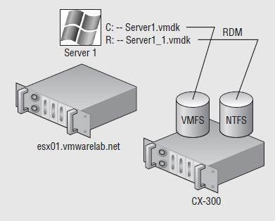
So, why choose one over the other if both are ultimately providing raw LUN access? Because the RDM in Virtual Compatibility mode uses a VMDK proxy file, it offers the advantage of allowing snapshots to be taken. By using the Virtual Compatibility mode, you will gain the ability to use snapshots on top of the raw LUN access in addition to any SAN-level snapshot or mirroring software. Or, of course, in the absence of SAN-level software, the VMware snapshot feature can certainly be a valuable tool. The decision to use Physical Compatibility or Virtual Compatibility is predicated solely on the opportunity and/or need to use VMware snapshot technology or when using physical to virtual clustering.
|
||||
A cluster-across-box configuration requires a more complex setup than a cluster-in-a-box configuration. When clustering across boxes, all proper communication between virtual machines and all proper communication from virtual machines and storage devices must be configured properly. Figure 11.4 provides details on the setup of a two-node virtual machine cluster-across-box configurations using Windows Server guest operating systems.
Make sure you document things well when you start using RDMs. Any storage that is presented to ESX and is not formattedwith VMFS will show up as available storage. If all the administrators are not on the same page, it is easy to take a LUN thatwas used for an RDMand reprovision that LUN as a VMFS datastore, effectively blowing away the RDM data in the process. I have seen this mistake happen firsthand, and let me tell you, the process is very quick to erase any data that is there. I have gone so far as to create a separate column in vCenter Server to list any RDM LUNs that are configured to make sure everyone has a reference point to refer to.
Let's keep moving and perform the following steps to configure Microsoft Cluster Services on Windows 2003 across virtual machines on separate ESX/ESXi hosts.
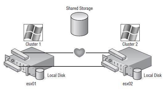
Figure 11.4
A Microsoft cluster built on virtual machines residing on separate ESX hosts requires shared storage access from each virtual machine using an RDM.
Creating the First Cluster Node in Windows 2003
Perform the following steps to create the first cluster node:
- Inside the vSphere client, create a virtual machine that is a member of a Windows Active Directory domain.
- Right-click the new virtual machine, and select the Edit Settings option.
- Click the Add button, and select the Hard Disk option.
- Select the Raw Device Mappings radio button, and then click the Next button.
- Select the appropriate target LUN from the list of available targets.
- Select the datastore location where the VMDK proxy file should be stored, and then click Next.
- Select the Virtual radio button to allow VMware snapshot functionality for the RDM, and then click Next.
- Select the virtual device node to which the RDM should be connected, as shown in Figure 11.5, and then click Next.
- Click the Finish button.
- Right-click the virtual machine, and select the Edit Settings option.
- Select the new SCSI controller that was added as a result of adding the RDMs on a separate SCSI controller.
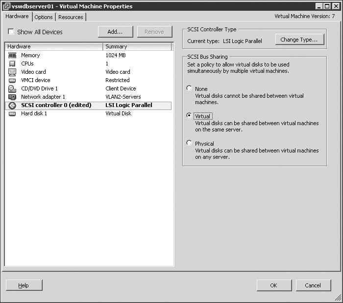
- Select the Virtual radio button under the SCSI Bus Sharing options, as shown in Figure 11.6.
- Repeat steps 2 through 9 to configure additional RDMs for shared storage locations needed by nodes of a Microsoft server cluster.
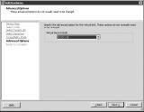
Figure 11.5
The virtual device node for the additional RDMs in a cluster node must be on a different SCSI node.
Figure 11.6
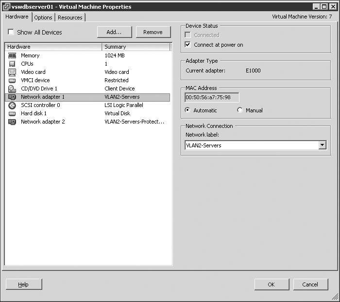
The SCSI bus sharing for the new SCSI adapter must be set to Virtual to support running a virtual machine as a node in a Microsoft server cluster.- Configure the virtual machine with two network adapters. Connect one network adapter to the production network, and connect the other network adapter to the network used for heartbeat communications between nodes. Figure 11.7 shows a cluster node with two network adapters configured.
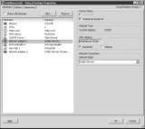
Figure 11.7
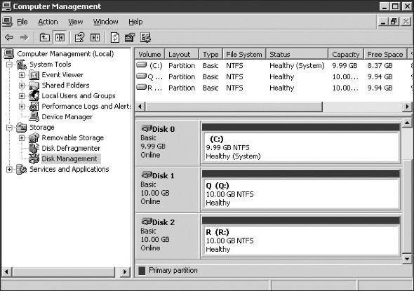
A node in a Microsoft server cluster requires at least two network adapters. One adapter must be able to communicate on the production network, and the second adapter is configured for internal cluster heartbeat communication.- Power on the first node of the cluster, and assign valid IP addresses to the network adapters configured for the production and heartbeat networks. Then format the additional drives, and assign drive letters, as shown in Figure 11.8.
- Shut down the first cluster node.
- In the VCenter Server inventory, select the ESX/ESXi host where the first cluster node is configured, and then select the Configuration tab.
- Select Advanced Settings from the Software menu.
- In the Advanced Settings dialog box, configure the following options:
- Set the Disk.ResetOnFailure option to 1.
- Set the Disk.UseLunReset option to 1.
- Set the Disk.UseDeviceReset option to 0.
-
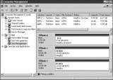
Figure 11.8
The RDMs presented to the first cluster node are formatted and assigned drive letters. - Proceed to the next section to configure the second cluster node and the respective ESX/ESXi host.
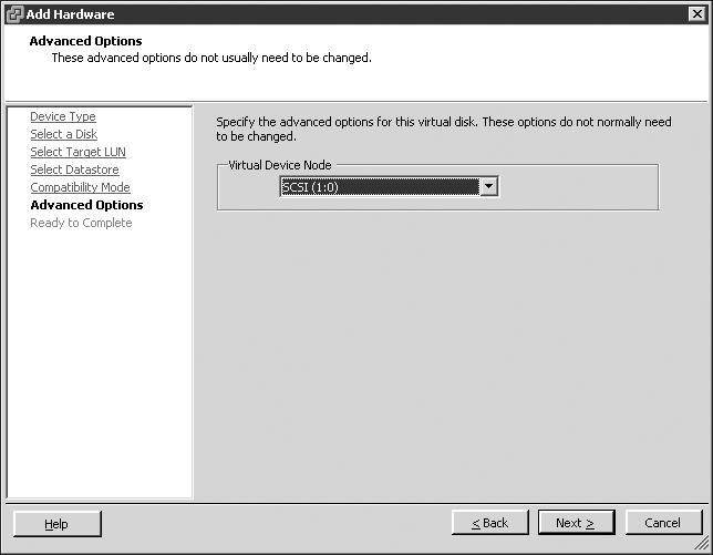
SCSI Nodes for RDMs
RDMs used for shared storage in a Microsoft server cluster must be configured on a SCSI node that is different from the SCSI to which the hard disk is connected that holds the operating system. For example, if the operating system's virtual hard drive is configured to use the SCSI0 node, then the RDM should use the SCSI1 node. This rule applies to both virtual and physical clustering.
Because of PCI addressing issues, all RDMs should be added prior to configuring the additional network adapters. If the NICs are configured first, you may be required to revisit the network adapter configuration after the RDMs are added to the cluster node.
Creating the Second Cluster Node in Windows 2003
Perform the following steps to create the second cluster node:
- Starting from inside the vSphere client, create a second virtual machine that is a member of the same Active Directory domain as the first cluster node.
- Add the same RDMs to the second cluster node using the same SCSI node values. For example, if the first node used SCSI 1:0 for the first RDM and SCSI 1:1 for the second RDM, then configure the second node to use the same configuration. As in the first cluster node configuration, add all RDMs to the virtual machine before moving on to step 3 to configure the network adapters. Don't forget to edit the SCSI bus sharing configuration for the new SCSI adapter.
- Configure the second node with an identical network adapter configuration.
- Verify that the hard drives corresponding to the RDMs can be seen in Disk Manager. At this point, the drives will show as a status of ''Healthy,'' but drive letters will not be assigned.
- Power off the second node.
- Edit the advanced disk settings for the ESX/ESXi host with the second cluster node.
Creating the Management Cluster in Windows 2003
Perform the following steps to create the management cluster:
- Starting from Active Directory Users and Computers, if you have the authority, create a new user account that belongs to the same Windows Active Directory domain as the two cluster nodes. The account does not need to be granted any special group memberships at this time.
- Power on the first node of the cluster, and log in as a user with administrative credentials.
- Click Start⇒Programs⇒Administrative Tools, and select the Cluster Administrator console.
- Select the Create New Cluster option from the Open Connection To Cluster dialog box. Then click OK.
- Provide a unique name for the name of the cluster. Ensure that it does not match the name of any existing computers on the network.
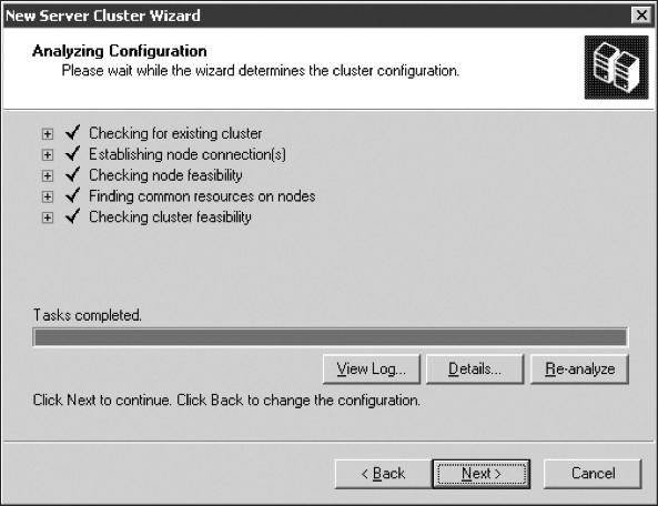
- The next step is to execute the cluster feasibility analysis to check for all cluster-capable resources, as shown in Figure 11.9. Then click Next.
-
Figure 11.9
The cluster analysis portion of the cluster configuration wizard identifies that all cluster-capable resources are available. - Provide an IP address for cluster management. The IP address configured for cluster management should be an IP address that is accessible from the network adapters configured on the production network. Click Next.
- Provide the account information for the cluster service user account created in step 1. The Cluster Service Account page of the New Server Cluster Wizard acknowledges that the account specified will be granted membership in the local administrators group on each cluster node. Therefore, do not share the cluster service password with users who should not have administrative capabilities. Click Next.
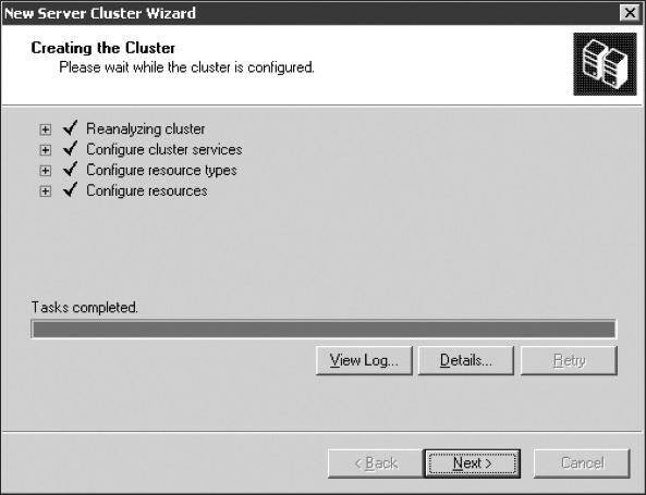
- At the completion of creating the cluster timeline, shown in Figure 11.10, click Next.
-

Figure 11.10
The cluster installation timeline provides a running report of the items configured as part of the installation process. - Continue to review the Cluster Administrator snap-in, and review the new management cluster that was created, shown in Figure 11.11.
Cluster Management To access and manage a Microsoft cluster, create a Host (A) record in the zone that corresponds to the domain to which the cluster nodes belong.
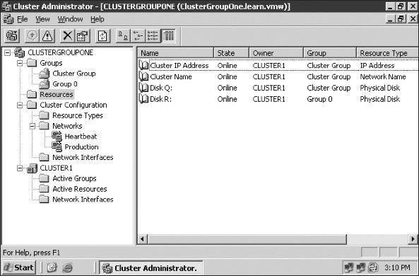
Figure 11.11
The completion of the initial cluster management creation wizard results in a cluster group and all associated cluster resources.
Adding the Second Node to the Management Cluster in Windows 2003
Perform the following steps to add the second node to the management cluster:
- Leave the first node powered on, and power on the second node.
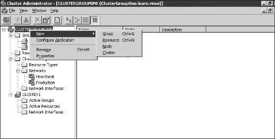
- Starting from the Cluster Administrator, right-click the name of the cluster, select the New option, and then click the Node option, as shown in Figure 11.12.
-

Figure 11.12
After the management cluster is complete, you can add a node. - Specify the name of the node to be added to the cluster, and then click Next.
- After the cluster feasibility check has completed (see Figure 11.13), click the Next button.
-
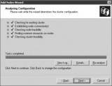
Figure 11.13
A feasibility check is executed against each potential node to validate the hardware configuration that supports the appropriate shared resources and network configuration parameters. - Proceed to review the Cluster Administrator, identifying that two nodes now exist within the new cluster.

Feasibility Stall
If the feasibility check stalls and reports a 0x00138f error stating that a cluster resource cannot be found, the installation will continue to run. This is a known issue with the Windows Server 2003 cluster configuration. If you allow the installation to continue, it will eventually complete and function as expected. For more information, visit http://support.microsoft.com/kb/909968.
At this point, the management cluster is complete; from here, application and service clusters can be configured. Some applications, such as Microsoft SQL Server 2005 and Microsoft Exchange Server 2007, are not only cluster-aware applications but also allow for the creation of a server cluster as part of the standard installation wizard. Other cluster-aware applications and services can be configured into a cluster using the cluster administrator.
Examining Physical to Virtual Clustering
The last type of clustering scenario to discuss is physical to virtual clustering. As you might have guessed, this involves building a cluster with two nodes where one node is a physical machine and the other node is a virtual machine. Figure 11.14 details the setup of a two-node physical to virtual cluster.
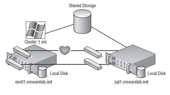
Figure 11.14
Clustering physical machines with virtual machine counterparts can be a cost-effective way of providing high availability.
The constraints surrounding the construction of a physical to virtual cluster are identical to those noted in the previous configuration. Likewise, the steps to configure the virtual machine acting as a node in the physical to virtual cluster are identical to the steps outlined in the previous section, with one addition: you must set the RDMs up in Physical Compatibility mode. The virtual machine must have access to all the same storage locations as the physical machine. The virtual machine must also have access to the same pair of networks used by the physical machine for production and heartbeat communication, respectively.
The advantage to implementing a physical to virtual cluster is the resulting high availability with reduced financial outlay. Physical to virtual clustering, because of the two-node limitation of virtual machine clustering, ends up as an N+1 clustered solution, where N is the number of physical servers in the environment plus one additional physical server to host the virtual machines. In each case, each physical virtual machine cluster creates a failover pair. With the scope of the cluster design limited to a failover pair, the most important design aspect in a physical to virtual cluster is the scale of the host running ESX/ESXi host. As you may have figured, the more powerful the ESX/ESXi host, the more failover incidents it can handle. A more powerful ESX/ESXi host will scale better to handle multiple physical host failures, whereas a less powerful ESX/ESXi host might handle only a single physical host failure before performance levels experience a noticeable decline.
Now that I've covered clustering, let's take a look at VMware's version of high availability. VMware has a built-in option called VMware High Availability that is just what the name implies.
![]()
![]() Ensuring High Availability and Business Continuity
Ensuring High Availability and Business Continuity
![]() Using Microsoft Cluster Services for virtual machine clustering
Using Microsoft Cluster Services for virtual machine clustering
![]() VMware HA implementation and ESX/ESXi host addition
VMware HA implementation and ESX/ESXi host addition
![]() HA cluster configuration: Requirements and steps
HA cluster configuration: Requirements and steps
Printed with permission from Wiley Publishing Inc. Copyright 2009. Mastering VMware vSphere 4 by Scott Lowe. For more information about this title and other similar books, please visit Wiley Publishing.