
Getty Images/iStockphoto
Maximize UPS capacity with three-phase power
A data center's UPS might not be overloaded. Check loads on the circuits and balance all three phases as closely as possible to obtain efficient capacity and energy out of the UPS.

Commercial buildings receive power in a three-phase configuration, which is different than the single-phase power delivered to homes. Three-phase power makes efficient use of transmission lines but requires a balance of loads on all phases to deliver maximum power.
Many uninterruptible power supplies have been replaced because an uneven power draw gave the appearance that the UPS was near overload. An unnecessary overnight replacement of a big UPS wastes money, disrupts an entire data center and exposes it to potential catastrophe. Follow these tips to avoid phase balance trouble in the data center.
Why three-phase?
UPS outputs are generally in a Wye configuration. European circuits use a phase leg and the neutral conductor, which makes balancing easier -- just move a plug from one outlet to another. That was also true with the American standard when data center hardware ran on 120 Volts. Today, however, data centers mostly use 208-Volt operation.
Three-phase legs connect in either Delta or Wye configurations. The Delta configuration doesn't provide a neutral conductor.
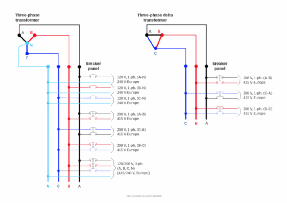
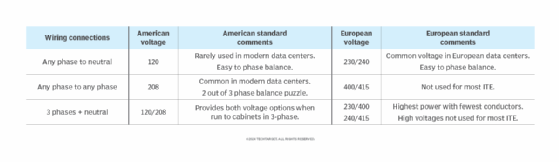
Figure 1 and Figure 2 illustrate the different American and European-standard voltages that derive from a three-phase, Wye-connected circuit. The Europe-standard voltages may be either 230/400 Volts or 240/415 Volts, as shown in Table 1. American legacy 110/220 Volts is obsolete, so is not shown. The ground wire, which is always necessary, is not shown for clarity.
Three-phase delivers more power to cabinets with fewer conductors. Copper, the labor to install more wiring and the larger conduits necessary to carry higher conductor counts are expensive. In legacy data centers where power draw is low and most hardware is single-corded, individual two-wire circuits connect to each cabinet. More power usage leads to an increase in two-wire circuits. Power demand also increases dual cording, doubled conductor counts.
IT systems have significant power demands, so it is common to run three-phase circuits to cabinets. Figure 3 illustrates the decrease in conductor counts when three-phase circuits undergo the two most common American and European current ratings. Higher amperage ratings are also in use today to further reduce circuit and conductor counts to high-density cabinets.
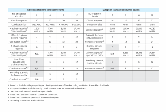
The much higher power capacities of European systems, even with amperage ratings seemingly lower than American systems, is because the phase to neutral voltage is 240 instead of 120 and their circuit breakers' energy are rated at full capacity. The National Electrical Code requires breakers to be de-rated to 80% for continuous current flow. Since IT systems often operate at a relatively constant load for extended periods, this derating factor is important. Many American data centers are now being constructed with European power systems to gain further efficiency.
The phase balancing challenge of three-phase circuits
Three-phase circuits deliver maximum power only when the loads on all three phases are equal. Loads will never be identical, but it is up to IT professionals to balance them as closely as possible. There should be no more than a 10% deviation from the median phase to the other two.
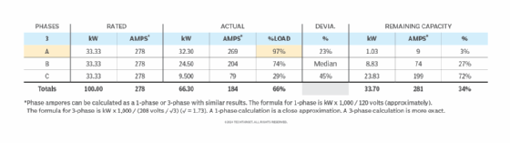
Figure 4 illustrates an American standard UPS where the phases are not balanced. Large UPS systems of 20 kilovolt amperes (kVA) and above will almost always be three-phase. The default or home display can be misleading when the load is shown to be on the heaviest loaded phase. In this example, a 100 kilowatt (kW) UPS is reading 97%, but that load is only on Phase A. The kW capacity on each phase is 1/3 the total UPS capacity, but the amperage is the same everywhere. This means there's still 34% of total capacity remaining, so UPS replacement would be a costly mistake.
Specific information is necessary to get loads as close to the same wattage or amperage as possible on all three phases of our UPS. If IT professionals use the UPS control panel to "drill down," they can read the actual loads on each phase and see how close to balanced they really are. If the UPS reads both kW and kVA, use the kW load. KW is known as the "real power" on a circuit.
Once IT professionals determine the load on each phase, the next step is to identify which cabinets or power strips connect to each phase. If that information is not illustrated anywhere, such as on the cabinet or receptacle, an electrician will need to decipher it. However, balancing phases at the UPS is difficult and often impractical since it requires re-connecting entire cabinets from one circuit to another. Even in data centers with the flexibility of overhead power busway, this task is laborious and might still lead to less-than-optimum phase balance.
Practical phase balancing
The place to accomplish phase balance is in the cabinets. This is simple in principle -- just move loads from one circuit to another. It's like solving an overload problem at home. As an example, there is a hair dryer, curling iron and a large-screen TV plugged into outlets in one room. Then a window air conditioner is plugged in. With the air conditioner on full blast, the TV on, and the curling iron and hair dryer on their highest settings, the load on the circuit is too much and causes everything to shut off. All outlets in the room are on the same circuit, which trips a breaker in the electrical panel.
This does not mean the whole house is out of power. One circuit is simply overloaded. There's plenty of power available, just like with the example UPS. To solve this dilemma, find an outlet on another circuit and re-allocate the load to better balance the available capacity. For instance, the curling iron and hair dryer can go into the bathroom while the TV and air conditioner plug into the adjacent room.
Load-balancing in the data center is the same process, except it's more critical and on a larger scale. Further, the receptacles on a three-phase power strip represent three different circuits. Conveniently, inverse time element loads are relatively constant. The only information and methodology necessary to balance loads should come from the cabinet power strips or manufacturer data.
Understand the three-phase iPDU load ratings
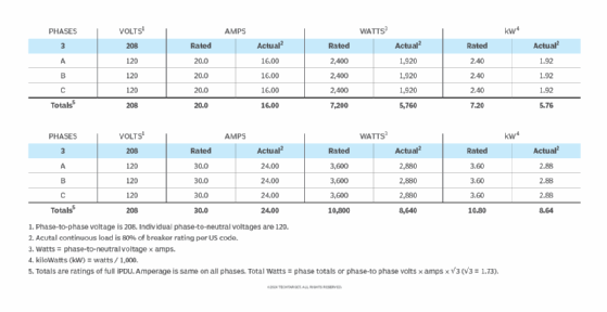
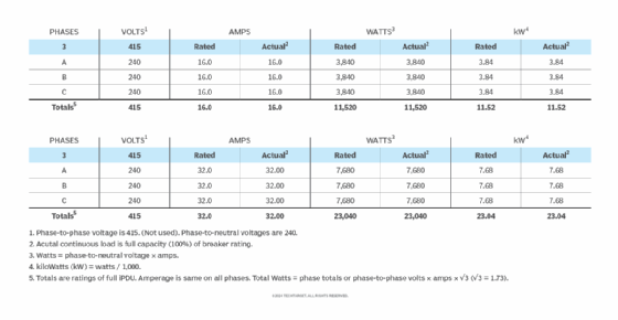
Shown below are the ratings of the two most popular sizes of three-phase intelligent power distribution units (iPDU's) in both American and European data centers. Figure 5 shows 20- and 30-amp American standard units. Figure 6 shows 16- and 32-amp European standard units. As described with Figure 3, European iPDU's can deliver much more power than similar American standard units.
Balancing phases in practice
There are two methods for phase balancing: trial and error as well as pre-planned circuit moves.
The trial-and-error method is the most difficult one. This is when you move plugs from one outlet to another and repeatedly check and recheck phase loads until balance improves. Most modern iPDU's provide the data to do this. If there are three simultaneous readouts, one for each phase), managers can instantly see the impact of load relocation. If there is a single display, users must toggle from phase to phase with a push button, write down the numbers, move the load and toggle through again to see the difference. This approach takes time and might expose equipment to shutdowns.
The faster approach is to pre-plan circuit moves on paper. Many modern iPDUs offer per-outlet readings that are accessible through the network. Alternatively, users can obtain reasonably accurate expected power draw information for each device. Use the spreadsheet charts below as templates to balance load per your devices. Add device rows, if necessary, to develop phase balance on paper before moving connectors around. The charts include all necessary formulas.
Figure 7 shows information technology equipment (ITE) connected to ten different outlets on a three-phase, European standard iPDU. Each 240-Volt connection is derived from one hot phase leg and the neutral on the plug strip. Equipment connection alternates phases across the strip. However, due to load differences, the phases are significantly out of balance. This is seen in the summary chart, which combines both wattage and amperage loads, then calculates percentages used, available power and phase balance deviations.
Note that both wattage and amperage load totals are simple additions in the European system.
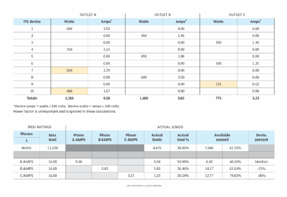
Figure 8 shows how moving three IT device connections to a different outlet results in a much closer phase balance, which is highlighted in light blue on both illustrations.
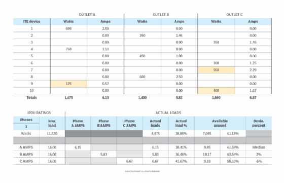
Figure 9 shows ITE connected to 10 different outlets on a three-phase American standard iPDU. Each 208-Volt connection derives from a different pair of the three hot phase legs on the plug strip, labeled A:B, B:C and A:C.
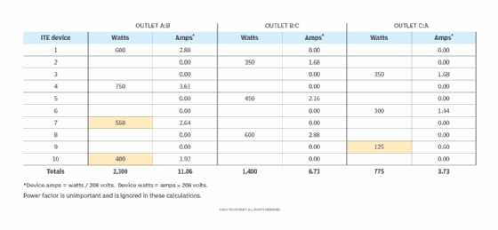
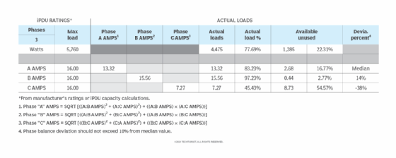
The loads on each of the three phase pairs are significantly out of balance. This can also be seen in the Figure 10 summary chart. The total loads on each phase leg are computed from the numbers in Figure 9.
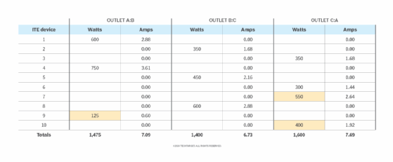
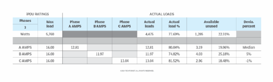
As shown in Figures 11 and 12 below, much closer phase balance is achievable on this iPDU by moving connections from three IT devices to different outlets, which are highlighted in light blue. The combination of phase loads is calculated using the same equations as in Figure 10.
Power monitoring is also necessary to maintaining phase balance going forward, as is planning power availability before making equipment additions. Recreate and use the above spreadsheets to make this an easier task.
Robert McFarlane is a principal in charge of data center design for the international consulting firm Shen Milsom and Wilke LLC. McFarlane has spent more than 35 years in communications consulting and has experience in every segment of the data center industry.