How to use dynamic reverse engineering for embedded devices
In this excerpt from 'Practical Hardware Pentesting,' read step-by-step instructions on how to find vulnerabilities on IoT devices using dynamic reverse engineering.
The proliferation of IoT has been accompanied by a proliferation of security vulnerabilities. Left unchecked, malicious attackers can use these weaknesses to infiltrate organizations' systems.
Regular penetration testing, long recognized as a security best practice, help security teams identify and mitigate vulnerabilities and weaknesses in embedded devices. Many organizations, however, limit pen testing to investigating networks and infrastructure -- IoT devices are often overlooked.
To get security teams up to speed on embedded device pen testing, Jean-Georges Valle, senior vice president at Kroll, a cyber risk and financial services consultancy, wrote Practical Hardware Pentesting: Learn attack and defense techniques for embedded systems in IoT and other devices.
In the following excerpt from Chapter 10, Valle details how pen testers can use dynamic reverse engineering to see how code behaves during execution on embedded devices. Valle provides an example of dynamic reverse engineering to show pen testers the challenges that may arise while observing how code behaves.
 Click here to learn more about
Practical Hardware Pentesting.
More on Practical Hardware Pentesting
Read an interview with Valle about embedded penetration testing, including common testing steps he uses, the difficulties of embedded pen testing and his opinion on how well organizations today secure embedded devices.
Editor's note: The following excerpt is from an early access version of Practical Hardware Pentesting, Second Edition and is subject to change.
Using dynamic reverse engineering -- an example
I've prepared a variant of the previous example that will pose us some challenges. I will show you how to overcome these challenges both statically and dynamically in order for you to be able to compare the amount of effort needed in both cases.
The rule of thumb when comparing dynamic and static approaches is that 99% of the time, dynamic approaches are just easier and should be given priority if possible (don't forget that you may not be able to get access to JTAG/SWD or other on-chip debugging protocols).
In this section, we will also learn how to break where we want, inspect memory with GDB, and all this good stuff!
The target program is located here in the folder you cloned, in the ch12 folder.
First, let's start by loading it into Ghidra and inspect it superficially. Pay attention to setting the correct architecture and base address in Ghidra's loading window (refer to the previous chapter if you don't remember how to do that or the base address value).
First Ghidra inspection
At first glance, the main function looks very similar to the main function in the previous chapter. We can find the reference to the main function by searching a PASSWORD string just like in the previous chapter and look into analyzing its structure.
I will let you work on the skills you acquired in the previous chapter to find the different functions. In this executable, you will find the following again:
- A big while (true) loop that acts as the main event loop and blinks the bluepill's LED while acting on a password being entered
- A function to initialize the clock
- A function to initialize the GPIOs
- A function to initialize the UART
- A value depending on the chip's unique identifier is calculated again in almost the same way (calculate this value for your chip and note this value down)
- A function validates the password (just before a big if that triggers either the printing of YOU WIN or NO)
- A function decrypts the winning string if the validation function returns an (uint16_t ) 0 value.
The similarity of the structure is intentional as this is your first time. If I were to repeat the exact same steps as in the previous chapter, it wouldn't give you anything new to learn, right?
Now, let's go through multiple methods of bypassing this password validation through dynamic interaction with the system. We will go from the most complex to the simplest in order to keep you focused and acquiring know-how (if you are anything like me, if there is an easy way to bypass something, why go for the hard way?).
Reversing the expected password
The first thing we're going to do is try to see how the password is validated to understand how to generate a password that passes the tests.
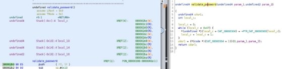
Let's have a look at the validation function equivalent C code that is output by Ghidra:
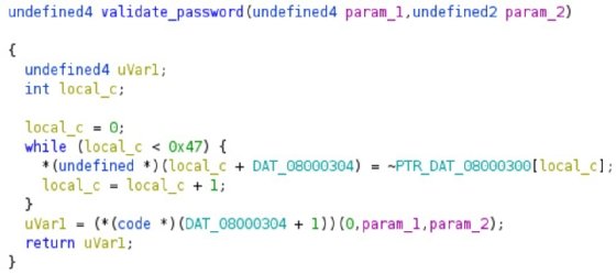
Humm... this is doing nothing directly with the parameters. This is copying the content of a 0x47 (71) long static array of bytes to RAM (and NOTs it) and then calls it as a function.
This is strange.
Or is it?
This is a very common technique to camouflage code (of course, a very simple version of it). If a clear version of the opcode is not present in the .bin file (and hence not in the flash of the MCU), a reverse engineering tool like Ghidra cannot detect that it is code! Here, we have two possible approaches:
- Either we manually extract the content of the buffer from the .bin file, decipher it (here, the cipher is just NOT'ing byte by byte, it is trivial on purpose), and have this be de-compiled by Ghidra.
- Or, since we have JTAG access to the chip, we can just put a breakpoint on the correct address in memory and let the MCU do the hard work for us.
I will leave the first solution for you to implement as an exercise. It should take more or less 10 lines of Python or C code for such a simple task! You want to be a hacker? Hack away!
Me? I'm a lazy guy. If a computer can work for me, well... So be it! I'll go for the second solution.
First, let's fire up a screen session in a terminal so we can enter passwords and see how it reacts:
screen /dev/ttyUSB0 115200
Let's fire up OpenOCD and GDB in a second terminal, as we did at the beginning of the chapter, and let's poke around:
openocd -f ./ftdi2232h.cfg.tcl -f ./clone_CSK.cfg & gdb-multiarch -x ./gdbinit
#openocd launching
[…]
target halted due to debug-request, current mode: Thread xPSR: 0x01000000 pc: 0x080013b8 msp: 0x20005000
[...]
And... and damn! It doesn't give me control back! No problem if that happens to you -- a little Ctrl + C will give you control back straight away:
^C
Program received signal SIGINT, Interrupt.
0x080003aa in ?? ()
(gdb)
After our Ctrl + C (^c), gdb tells us that the execution is stopped at address 0x080003aa in an unknown function (??).
Depending on your specific state, you may break at another address.
Do not panic -- put your thinking hat on and take your towel with you (always).
This is not a problem. The chances are that you will be breaking very near this address since it is in the waiting loop that blinks the LED, waiting for a password to be received on the serial interface.
First things first, let's have a look at our registers:
(gdb) i r
r0 0x0 0
r1 0x8001a1d 134224413
r2 0x5b8d7f 5999999
r3 0x335d7 210391
r4 0x20004f88 536891272
r5 0x8001a74 134224500
r6 0x0 0
r7 0x20004f88 536891272
r8 0x0 0
r9 0x0 0
r10 0x0 0
r11 0x0 0
r12 0xf 15
sp 0x20004f88 0x20004f88
lr 0x80003bf 134218687
pc 0x80003aa 0x80003aa
xPSR 0x81000000 -2130706432
msp 0x20004f88 0x20004f88
[...]
We see that pc is indeed where it is supposed to be, everything looks fine and dandy. So, now let's try to enter a password.
And... nothing works on the serial interface window! Thinking hat on... GDB is actually blocking the execution of the code; the serial interface will not react to your inputs. This is normal.
So, let's allow it to continue (continue or c in the gdb window) and see if the serial works now. Yes, it does. Let's break it again and put a breakpoint on the address of the password validation function, shall we?
In Ghidra, we can see that the address of the first instruction of the function is 0x080002b0:
Let's put a breakpoint there, let gdb resume execution, and enter a dummy password:
(gdb) b * 0x080002b0
#1
Breakpoint 1 at 0x80002b0
#2
(gdb) c
#3
Continuing.
Note: automatically using hardware breakpoints for read-only addresses.
#4
[entering 'aaa' in the serial console and enter]
Breakpoint 1, 0x080002b0 in ?? ()
#5
(gdb)
Let's dissect that:
- b * 0x080002b0 asks gdb to put a breakpoint on the instruction stored at address 0x080002b0. Check your pointers.
- gdb tells me, Okay, I've put a breakpoint there.
- Continue the execution please, my dear gdb and it says it is happy to do so.
- BUT it notifies me that it can't write at address 0x080002b0 (it is in flash and flash cannot be written just like that; it has to be unlocked and written chunk by chunk). In order to avoid doing so much back and forth, ARM chips come with some internal debug systems that allow it to break when pc hits specific addresses that cannot be easily written to).
- Bam! The breakpoint has been hit! The execution is stopped after I enter a dummy password.
Okay, now what can we do with that?
First things first, if you remember the code of the validation function, its arguments were passed directly to the decoded code. Let's have a look at what they can be (remember the calling convention for functions: arguments are in r0-3):
(gdb) p/x $r0
$2 = 0x20000028
(gdb) p/x $r1
$3 = 0x2169
The first argument is something in RAM, and the second is some kind of value. (This is the transformed UUID value for your chip, which you noted down, right?)
Now, what is stored at this first address? Let's examine it:
(gdb) x/x 0x20000028
0x20000028: 0x00616161
(gdb) x/s 0x20000028
0x20000028: "aaa"
Ah! Ah! Ah! (See what I did there?) This is our password. Please note the usage of the format modifier for the x command.
So, this is expected.
Now let's look into the deciphered code.
Ghidra tells us that the instruction that follows the decoding loops is at 0x080002f0. Let's break there:
(gdb) b * 0x080002f0
Breakpoint 2 at 0x80002f0
(gdb) c
Continuing.
Breakpoint 2, 0x080002f0 in ?? ()
(gdb) c
(gdb) x/4i $pc
=> 0x80002f0: movs r0, #0
   0x80002f2: blx r3
   0x80002f4: mov r3, r0
   0x80002f6: mov r0, r3
So, the address of the deciphered code is in r3. We saw the buffer was 0x47 (71) long. We are in thumb mode (so size 2 instructions). This should be 47/2 : about 35 instructions. The last bit of the address is for the mode; we can get rid of that:
(gdb) x/35i ($r3 & (~1))
   0x20000128: push {r4, r5, r6, r7, lr}
   0x2000012a: eors r4, r4
   0x2000012c: eors r3, r3
   0x2000012e: eors r5, r5
   0x20000130: ldrb r5, [r1, r4]
   0x20000132: mov r8, r5
   0x20000134: mov r6, r8
   0x20000136: lsrs r6, r6, #4
   0x20000138: lsls r5, r5, #4
   0x2000013a: orrs r5, r6
   0x2000013c: movs r6, #255 ; 0xff
   0x2000013e: ands r5, r6
   0x20000140: movs r6, #15
   0x20000142: mov r8, r4
   0x20000144: mov r7, r8
   0x20000146: ands r7, r6
   0x20000148: add r6, pc, #16 ; (adr r6, 0x2000015c) #1
   0x2000014a: ldrb r6, [r6, r7]
   0x2000014c: eors r5, r6
   0x2000014e: adds r0, r0, r5
   0x20000150: adds r4, #1
   0x20000152: ldrb r5, [r1, r4]
   0x20000154: cmp r5, r3
   0x20000156: bgt.n 0x20000132
   0x20000158: eors r0, r2
   0x2000015a: pop {r4, r5, r6, r7, pc}
   0x2000015c: str r5, [r4, #36] ; 0x24
   0x2000015e: ldrb r4, [r6, #5]
   0x20000160: ldr r7, [r6, #32]
   0x20000162: subs r2, #55 ; 0x37
   0x20000164: ldr r4, [r2, r5]
   0x20000166: ldr r5, [r1, #100] ; 0x64
   0x20000168: add r3, r12
   0x2000016a: adds r4, #68 ; 0x44
   0x2000016c: vqadd.u8 q0, q8, <illegal reg q15.5>
That's more like it! We see a normal function prelude (saving intra-function registers to the stack), some processing, and a function return. But GDB warns us about illegal instruction parameters (0x2000016c).
When looking at the listing, we see that GDB indicates the usage of a PC relative piece of data:
#1 : commented : adr r6, 0x2000015c)
This is very often used to store data in an assembly program. adr is a pseudo instruction that tells the assembler, please add the offset to a label (a named position) in the code.
Let's look at what is stored there:
(gdb) x/4wx 0x2000015c
0x2000015c: 0x79746265 0x3a376a37 0x6e4d5954 0x34444463
(gdb) x/s 0x2000015c
0x2000015c: "ebty7j7:TYMncDD4"
This is indeed a string that is used in the process somehow.
Let's step through the first instructions, as an example of how to follow an execution flow. We will first set up gdb so it shows us the interesting registers, content on each step:
(gdb) disp/x $r0
1: /x $r0 = 0x20000028
(gdb) disp/x $r1
2: /x $r1 = 0x20000028
(gdb) disp/x $r2
3: /x $r2 = 0x2169
(gdb) disp/x $r3
4: /x $r3 = 0x20000129
(gdb) disp/x $r4
5: /x $r4 = 0x20004f88
(gdb) disp/x $r5
6: /x $r5 = 0x8001a74
(gdb) disp/x $r6
7: /x $r6 = 0x0
(gdb) disp/x $r7
8: /x $r7 = 0x20004f70
(gdb) disp/x $r8
9: /x $r8 = 0x2
(gdb) disp/i $pc
10: x/i $pc
=> 0x80002f0: movs r0, #0
=> 0x80002f2: blx r3
Now we are ready to use stepi (step instruction) to see what is going on:
0x2000012b: eors r4, r4
0x2000012d: eors r3, r3
0x2000012f: eors r5, r5
This zeros r4, r3, and r5 (x^x = 0):
0x20000130: ldrb r5, [r1, r4]
0x20000132: mov r8, r5
0x20000134: mov r6, r8
This loads the first character of the password string in r5 (r1 is the address and r4 is zeroed at this point) and copies it to r8 and r6:
0x20000136: lsrs r6, r6, #4
0x20000138: lsls r5, r5, #4
0x2000013a: orrs r5, r6
0x2000013c: movs r6, #255 ; 0xff
0x2000013e: ands r5, r6
This shifts r6 4 bits to the right, r5 4 bits to the left, and puts their ORed value in r4. It then masks out the ORed result with 0xff, basically exchanging the 4 lower and 4 higher bits of the password character and cleaning out the excess bits!
0x20000140: movs r6, #15
0x20000142: mov r8, r4
0x20000144: mov r7, r8
0x20000146: ands r7, r6
This moves 15 in r6, copies r4 in r8 and r7, and masks r7 with 15. But why? At this point, r4 is 0! This may be used later -- since we saw that r4 was used as an offset on the loading of the password character, r4 is probably a counter! If that is the case, this masking can be used as a kind of modulo... (it's very common to use masking for modulo a power of two -1):
0x20000148: add r6, pc, #16 ; (adr r6, 0x2000015c)
0x2000014a: ldrb r6, [r6, r7]
This loads the first character of the string that was hidden in r6 and uses r7 and an offset! r4 is definitely a counter here and r7 a modulo'ed version of it. This is a very typical programming way to approach this:
0x2000014c: eors r5, r6
0x2000014e: adds r0, r0, r5
0x20000150: adds r4, #1
This is XORing the value of the bit swapped password character with the current ranks of the strange string, adding this to r0 and incrementing the r4 counter:
0x20000152: ldrb r5, [r1, r4]
0x20000154: cmp r5, r3
0x20000156: bgt.n 0x20000132
This loads a new password character with the new offsetting r5. r3 is 0 so the cmp checks r5-r3 and ... Wait … bgt.n? What is that? Do you remember what to do when you have doubts? Go read the documentation here: https://community.arm.com/developer/ip-products/processors/b/processors-ip-blog/posts/condition-codes-1-condition-flags-and-codes.
So, it jumps if r5 > r3. And r3 is 0, so? This is testing for a 0 terminated string!
This is the main validation logic loop!
Once this is done, it does this:
0x20000158: eors r0, r2
0x2000015a: pop {r4, r5, r6, r7, pc}
It XORs this sum with the UUID depending on the value it calculated, restores the caller register values, and returns this value. The C code then checks whether this value is null to actually display the winning string. We then just need to arrange it so that our sum is equal to the UUID dependent value for the XOR to be null!
We have the whole logic!
Dig Deeper on Threats and vulnerabilities
-
![]()
An introduction to network automation with Ansible
By: Charles Uneze
-
![]()
Pure//Accelerate 2023 : les baies FlashArray R4 sont 40 % plus rapides
By: Yann Serra
-
![]()
Pure takes aim at HDDs with FlashArray for colder storage
By: Adam Armstrong
-
![]()
Tenable opens playground for generative AI cyber tools
By: Alex Scroxton