
Edelweiss - Fotolia
Choosing from a universe of SSD form factors
There are a number of different types of SSD storage form factors to choose from. Learn more about each different type, along with their advantages.

SSDs come in a wide array of form factors. Let's review a number of them to get a better understanding of where they fit.
SSDs come in a wide variety of mechanical outlines and pin configurations. This article is intended to clarify some of the confusion users might encounter in choosing the type of SSD that best fits a given situation.
At a top level, SSDs are not only specified by their capacity in gigabytes or terabytes, their speed (using various measures we won't go into here), or, naturally, their price. They also fit into a range of interface types and physical dimensions, the combination of which is often referred to as the SSD's form factor. A drive might be referred to as 2.5-inch SATA (alternatively, 2.5" SATA) or 2230 NVMe.
Let's look at some of the most common categories of SSD to get a basic feel for how all of this works.
Legacy HDD form factors: ATA & SCSI and their progeny
Until the early part of the 21st century, SSDs were an expensive option for certain niche applications and needed to conform to the rest of the computing industry to gain acceptance. This meant that they not only matched the interfaces of hard disk drives (HDDs), but they also, in many cases, were made to match the mechanical outlines of HDDs, whose outside dimensions were worked around the size of the disk within the package. By that time, the HDD industry had settled down to two leading disk diameters: 2.5-inch and 3.5-inch. These communicate using either of two standard interfaces:
- ATA -- AT Attachment, referring to IBM's PC-AT of the early 1980s, also called IDE for Integrated Drive Electronics.
- SCSI -- Small Computer System Interface.
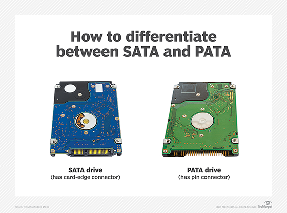
When SSDs began to gain widespread use, the ATA interface was determined to be slow enough to hinder the SSD's high-speed capabilities, yet SCSI, while faster, was costly to implement, so a faster serial version of the ATA protocol was introduced and named Serial ATA or SATA. With this, the original ATA interface took on a new name of PATA for Parallel ATA.
The SCSI camp emulated the benefits of SATA, introducing the Serial-Attached SCSI interface, or SAS for short.
Although many PATA SSDs are still available, they are largely a niche product provided by specialty suppliers for legacy systems. PATA SSDs are typically aimed at industrial automation applications, and are made in non-standard mechanical dimensions that are smaller than the HDDs they mimic.
The markets for PATA and SCSI SSDs have largely been taken over by SATA and SAS SSDs, both of which ship in HDD-format 2.5" and 3.5" packages and are still used in volume today. These two interfaces have gone through successive speed increases that can be serviced by SSDs, but that are much faster than any HDD.
SATA SSDs are broadly used in everything from older PCs and desktops to servers and storage arrays. Most SATA SSDs sell in a 2.5-inch form factor, whose dimensions replicate those of a 2.5" HDD. Although SATA SSDs are not a growing market, the format should continue to be widely available for several more years.
SAS SSDs are largely used in storage arrays, but even in that application they are in decline as they are replaced with one or more of the PCIe-based SSDs listed below. Nonetheless, SAS SSDs remain widely available and are typically sold in a package whose dimensions match those of a 3.5" HDD.
PCIe-based form factors: HHHL, AIC, NVMe
Another change was happening at about the same time that SSD acceptance became widespread. HDD users who needed speed and large capacities would often connect multiple HDDs to a system using a RAID controller or a host bus adapter (HBA). Both of these were cards that managed a number of HDDs, channeling their communications to the CPU through the PCIe interface (Peripheral Component Interface, Express).
Systems that required extreme speed would sometimes connect then-costly SSDs together using an HBA or RAID card.
Enterprising SSD developers, led by the PCIe SSD innovator Fusion-IO, streamlined these systems by combining the chips from multiple SSDs and an HBA or RAID controller onto a single PCIe card, typically using one of the smaller PCIe formats that was half the full height and half the length (HHHL, for half-height, half-length) of a full-size PCIe card. This SSD format also adopted the name Add-In Card, or AIC.

PCIe SSDs provided great speed advantages over HBA-connected or RAID-connected HDDs, but they had limited capacities since a PCIe SSD was powered by the PCIe connector, which only delivered 25 Watts. (HDDs connected using a RAID or HBA card were provided with their own power cord.) This problem was addressed with successive updates to the PCIe standard to support high power draws, allowing larger PCIe SSDs to be developed.
These HBA-based and RAID-based PCIe SSDs suffered from another disadvantage -- HBAs and RAID arrays had never been configured to allow the host server to boot from them, so new standards and software had to be developed. In addition, there were no protocol standards for HBAs and RAID cards, so every PCIe SSD used a different protocol than its competitors.
While individual companies dealt with these issues in their own way, an industry consortium formed to devise standards to allow PCIe SSDs to be interchanged -- and the Nonvolatile Memory Express (NVMe) standard protocol was developed. NVMe, which communicates over the PCIe interface, was developed as a forward-looking protocol that not only solved several NAND flash SSD issues, but it also paved the path for other memory technologies to be used as storage without requiring changes to existing software.
NVMe-enabled PC form factors
A whole new world opened to SSDs with the adoption of NVMe. Now systems could boot from their PCIe-attached SSDs, allowing a single NVMe SSD to serve as the only storage in the system.
SSDs could also provide storage in a much thinner form factor than an HDD, so the thinnest notebook PCs began to use a new form factor of SSD that supported the SATA interface on an unenclosed single-sided PC card. Computer designers determined that the PCIe protocol could support higher throughput than SATA and drove the creation of the m.2 form factor, a very small-format SSD that consumes far less space and can fit within the smallest PC form factor chassis, taking up far less space than the SATA SSDs that PCs originally used. This was an enabler for the "Thin and Light" PC form factor that is so popular today.

The m.2 format was developed before the use of PCIe as an SSD interface became prevalent, so the format can be purchased with either a PCIe or a SATA interface. Card edge keys prevent users from plugging a PCIe m.2 SSD into a SATA slot and vice versa. Use of the SATA interface in the m.2 format has faded over time, though, and m.2 SATA SSDs are now uncommon.
The m.2 format is typically a bare PC card that combines two standard widths of 22mm and 30mm (with several others defined), and multiple lengths. Several standard thicknesses support single-sided boards with the smallest dimensions for thin-and-light PCs, plus a variety of other thicknesses to support double-sided boards and heat sinks. An SSD that is referred to as "m.2 2280" is 22mm wide and 80mm long.
Hot-swappable formats
At roughly the same time that m.2 was being standardized, the U.2 format evolved to provide an enclosed version of the original HHHL PCIe format. The enclosure supports hot-swapping the SSD for front-panel replacement in rack-mount applications. This became necessary as the high-speed PCIe interface gained mass popularity in large-scale datacenters. Datacenter users were accustomed to hot-swapping out failed storage devices from the server's front panel, and before the advent of U.2, PCIe neither supported hot swap, nor front-panel access. The new U.2 standard was developed to allow this.
But U.2 SSDs can't fit into a 1U "Pizza Box" format server, a form factor that was becoming prevalent at the time that m.2 was introduced. Both the then-standard PCIe SSD add-in card format and the new U.2 SSD were too large to use in a 1U server. This led to the development of small form factor hot-swappable PCIe SSD form factors for use in datacenters.
To fulfil this need, smaller formats were introduced, that not only supported hot swapping in a 1U chassis, but also put a greater focus on the critical issue of rack module airflow. This format is called EDSFF, for Enterprise and Datacenter Standard Form Factor.
EDSFF SSDs are available in two lengths, named Long (E1.L, 318.75mm) and Short (E1.S, 111.49mm or 118.75mm). Both support multiple thicknesses to accommodate thicker PC boards with flash chips on both sides, and perhaps more importantly, heat sinks, since these SSDs operate at high speeds in server environments. These SSDs' high speeds cause them to dissipate a lot of power, and servers are already known for their internal heat management issues. The narrow width of these SSDs (31.5mm-33.75mm) allows them to fit within a 1U server chassis and to support front-panel removal. Another less common format is similar but wider (76mm), as it was designed for use in a 2U chassis. This is called the E3.S and E3.L format. Many of today's highest-capacity SSDs, now in the hundreds of terabytes, are offered in these formats.
Future directions
The industry has settled on the PCIe interface for most SSDs, and will continue to track new PCIe generations. However, less-frequent updates are expected for the NVMe protocol, which layers on top of PCIe to support SSDs. It appears today that the biggest changes we should anticipate involve the creation of giant-capacity QLC SSDs of hundreds of terabytes to support hyperscale AI datacenters. Liquid cooling is being explored by Solidigm, while companies like IBM and ScaleFlux have tapped into the SSD's internal smarts to offload from the host both mundane tasks like data compression to more sophisticated routines like monitoring read/write activity for ransomware attacks.
The industry continues to explore new directions. Samsung has spent a considerable effort to fit an SSD onto the CXL protocol, which is based around memory semantics rather than file/block semantics. Their prototype, originally dubbed the memory-semantic SSD or MS-SSD, has been rechristened to CMM-H TM for "CXL memory module, hybrid, tiered memory." It’s too early to tell if such a product will meet with market success.
Internal to SSDs there have been various efforts to include hooks to allow the host system more optimized control of the SSD's internal management. With streams, for example, data is stored in alignment with the process that is using it. Another example includes key value storage, which promises to revolutionize storage to take advantage of the intelligence now available within storage, abandoning the timeworn approach of having the host manage individual addresses within the storage device.
SSDs, like any technology, will go through important changes as technology continues to progress. The field will continue to provide greater opportunities and larger capacities.
Jim Handy is a semiconductor and SSD analyst at Objective Analysis in Los Gatos, Calif.