
Sergey Nivens - Fotolia
Increase data center efficiency with the NSX-T load balancer
When creating a load balancer, the NSX-T Data Center software is a likely contender, but you must have the necessary NSX-T components, such as tier 0 and tier 1 routers, before beginning.

Certain workloads within your virtual data center systems might require a load balancer to improve availability, network efficiency and capacity.
Depending on your data center's scale and required features, the load balancer in VMware's NSX-T Data Center might be sufficient.
Similar load balancing has been available in NSX Data Center for vSphere for years and though the engine has changed, the majority of the functionality is the same.
Before setting up the load balancer in NSX-T Data Center, there are a few necessary NSX-T components that you must have depending on your chosen load balancer topology.
Inline vs. one-arm load balancers
There are two options when it comes to load balancing: inline or one-arm. You can easily place a one-arm load balancer in an existing network.
As you can see in the image below, the clients and servers can exist within the same network. As a result, there is no need to change your networking layout to introduce this load balancer.
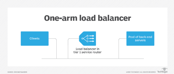
However, a one-arm load balancer does have disadvantages. This topology performs network address translation on the source address and then forwards the packets to one of the back-end servers. That server then sends its return packets to the one-arm load balancer, which then forwards it to the originating client.
The problem is that the back-end server never knows who the actual client is, which can become an issue when the system has session persistence. The NSX-T load balancer does support X-HTTP-Forwarded for header injection, but it only works for Layer 7 HTTP applications; your server application must also support X-HTTP-Forwarded.
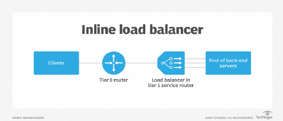
When you implement a load balancer in your networking topology, you are better off with an inline load balancer. There isn't a one-arm or inline checkbox in the NSX-T Data Center software; you can change a one-arm load balancer to an inline by connecting the NSX-T load balancer to two different network segments. As a result, the inline load balancer will route traffic to a back-end server.
During this process, the inline load balancer maintains the original source address and the back-end server then sends its reply, which you can use for session persistence. The image below shows an inline load balancer where the clients connect from behind a tier 0 logical router. The clients themselves can originate anywhere within your network or even from an external network.
Create an NSX-T load balancer
Both the one-arm and inline NSX-T load balancers run within a tier 1 logical router, which is part of an edge transport node. The edge transport node is often a VM, but it can also be a bare-metal transport node. When you create an NSX-T load balancer, the tier 1 router must already exist. You must also have a tier 1 logical router to connect clients from the physical network to the tier 0 logical router.
The first step to create the load balancer from the NSX-T user interface is to add a load balancer instance. You can choose the load balancer deployment size from the NSX-T Data Center software client.
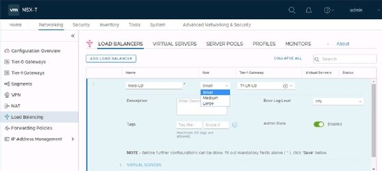
The choice for the deployment size -- small, medium or large -- is related to the number of virtual servers, pools and pool members within your system.
For example, if you have 20 virtual servers, 60 pools and 300 pool members, you should choose the small deployment option. If you have 100 virtual servers, 300 pools and 2,000 pool members, you should choose the medium deployment option. If you have 1,000 virtual servers, 3,000 pools and 7,500 pool members, you should choose the large deployment option.
Next, you must define a virtual server, which requires an IP address, a Layer 4 TCP/UDP or Layer 7 HTTP and a port. This enables you to send a request from the given port address to one of the back-end servers. Afterward, you must create the server pool, which requires you to create a list of server IP addresses and ports where to send traffic.
Configure the load balancing algorithm settings
After you define the virtual server, the NSX-T Data Center software configures two important components: the load-balancing algorithm and the monitor, which is how you determine whether a back-end server is present or not. Round Robin is the default choice for load-balancing algorithms.
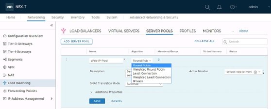
This means that the software distributes your clients one by one to the back-end servers without taking into consideration how busy those servers are.
You must also choose an appropriate monitor, which ensures clients have a back-end server to connect to. The NSX-T load balancer comes with default monitors to perform an HTTP(S) request, an ICMP request or to setup a TCP connection.
You can also create your own monitor definitions to access a specific HTTP URL and check for a specific response body, or to set up a TCP or UDP connection with a specific port. Custom definitions let you configure how often to test a host and to determine how many failures are acceptable before the host is made unavailable.
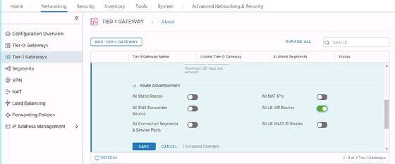
The load balancer setup is complete once you configure the algorithms and monitors. You must not forget to configure your tier 1 logical router to distribute the load balancer virtual IP addresses to other routers. For this, you enable the All LB VIP Routes under route redistribution for your tier 1 logical router from the NSX-T Data Center software.
Dig Deeper on Containers and virtualization
-
![]()
VMware remakes NSX for companies using multiple clouds
By: Antone Gonsalves
-
![]()
How to deploy Kubernetes on VMware with vSphere Tanzu
By: Rob Bastiaansen
-
![]()
VMware Tanzu service mesh tie-in syncs multi-cloud networks
By: Beth Pariseau
-
![]()
VMware NSX vs. Microsoft Hyper-V network virtualization
By: Rob Bastiaansen