Intro to encapsulation and decapsulation in networking
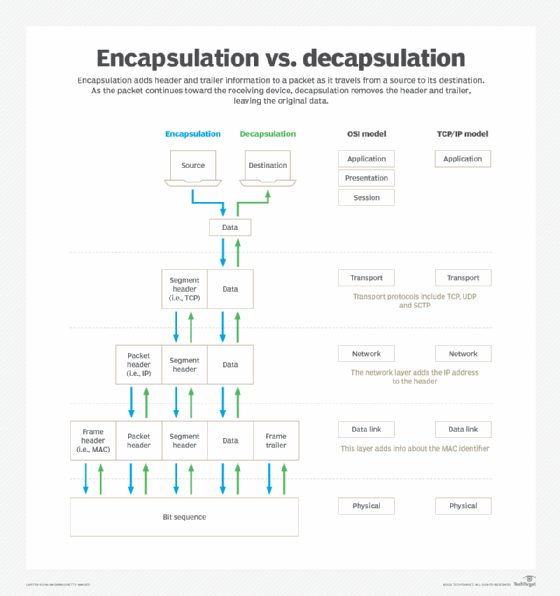
Encapsulation adds information to a packet as it travels to its destination. Decapsulation reverses the process by removing the info, so a destination device can read the original data.
Many people take networks for granted, despite the significant roles they play in our daily lives. Networks rely on a few basic concepts, some of which include encapsulation, decapsulation and network layers.
What is encapsulation?
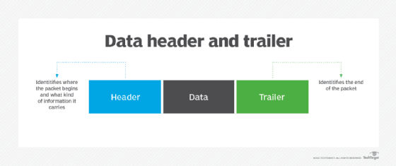
Encapsulation marks where a packet, or unit of data, begins and ends. The beginning part of a packet is called the header, and the end of a packet is called the trailer. The data between the header and trailer is sometimes referred to as the payload.
The packet header carries information in its first few bytes to mark where the packet begins and to identify the type of information it carries. As a packet travels from its source to a destination, different layers in a computing system contribute to the packet header. The header info varies depending on which protocol is used, as each protocol has a defined format.
The packet trailer indicates to a receiving device that it has reached the end of the packet. It often contains an error-check value that the receiving device can use to confirm it has received the full packet.
A basic data packet with a header and trailer
What is decapsulation?
Decapsulation is the process of removing the header and trailer information from a packet, as it moves toward its destination. The destination device receives the data in its original form.
The OSI model and encapsulation
ISO defined a model for protocols that separates system layers by function: the Open Systems Interconnection (OSI) model. Each of the seven OSI layers provides a specific set of functions.
Decapsulation is the process of removing the header and trailer information from a packet, as it moves toward its destination.
In the encapsulation process, a source computer sends a packet from Layer 7, the application layer, to Layer 1, the physical layer. Data encapsulation doesn't begin until a packet reaches Layer 4, the transport layer. After that, the remaining layers add corresponding information to the packet, enabling it to travel through the system.
Decapsulation moves in the reverse order, from Layer 1 to Layer 7 in the OSI model, as the packet travels to the receiving computer.
Layer 1: Physical
This is the lowest layer that manages the electrical signals of a network device in use. The physical layer adds the bit sequence that marks the beginning of the packet and the trailer.
Layer 2: Data link
The link layer manages the interaction across the local network between the sending and receiving systems. In encapsulation, it adds the local destination address to the header.
Layer 3: Network
The network layer routes the packet across the network. It encapsulates the packet with the internet address header.
Layer 4: Transport
Some transport protocols, such as Transmission Control Protocol (TCP), guarantee that all packets reach their destination. Other transport protocols do not guarantee delivery, such as User Datagram Protocol (UDP). Transport protocols add byte counts to headers.
Layer 5: Session
The session layer manages the flow of information between systems. It provides information about how the information is allowed to flow throughout the system.
Layer 6: Presentation
The presentation layer modifies the information to a form an application can use. It provides information about data formats.
Layer 7: Application
As the highest layer, the application layer interacts with the end device.
Compare how encapsulation and decapsulation work in the OSI and TCP/IP models.
The TCP/IP model and encapsulation
The most widely used network protocols are in the Internet Protocol suite, commonly referred to as TCP/IP, which was developed under contract by the U.S. Department of Defense. The TCP/IP model was designed to operate on a variety of computer types.
While the TCP/IP model follows the same design principles as the OSI model, the two differ. The main difference is the TCP/IP model consolidates Layers 5 through 7 of the OSI model into a single application layer. It also commonly combines the physical and data link layers, sometimes called the network interface or network access layer.
The encapsulation and decapsulation processes with TCP/IP follow the same progression through the layers as with the OSI model.
Network interface layer: Physical and data link
The lowest layer, the physical layer, encapsulates the packet, adding a bit sequence specific for each type of network medium. Each type of network -- e.g., Ethernet, fiber and Wi-Fi -- operates differently. Therefore, the sequence of bytes that marks the beginning of a packet differs for each. The trailer format also varies by type of medium.
Every packet makes its first hop across the local network. The data link layer adds the media address control (MAC) identifier, which is installed in each network interface by the system manufacturer. The first bytes identify the manufacturer, and the following bytes uniquely specify every network interface that the manufacturer has ever produced. Consequently, no two interfaces worldwide have identical MAC addresses.
When a packet is sent, every system that shares a local network reads that packet's destination MAC address. But only the system with that specific assigned MAC address reads the remainder of the packet.
Network layer
The network layer routes the packet through the larger network. In many cases, the first hop across the local network, which the data link layer handles, takes the packet to a system with a router.
The packet requires an internet address to address the destination system across the larger network. The network layer adds the destination internet address -- which is assigned to a system when it is installed in the network -- to the packet header.
Transport layer
A variety of transport protocols are available, including TCP, UDP and Stream Control Transmission Protocol (SCTP):
TCP guarantees packet delivery with all packets received and acknowledged. It adds the number of bytes sent in the packet to the header and waits for the receiver to respond with the number it is acknowledging. The receiver also adds the number of bytes that it is now prepared to receive in order to prevent the sender from overwhelming it by sending data too fast.
UDP does not guarantee delivery, but it is a valuable protocol for latency-sensitive applications, such as voice or video, where losing a packet is better than spending the time to resend lost packets.
SCTP can send data and control information in separate, simultaneous streams.
Application layer
The TCP/IP model combines the session and presentation layers into the application layer. Session can control whether a connection transmits in both directions simultaneously, one direction at a time or simply in one direction.
The presentation layer operates above session and ensures that the application receives data in a usable form. It can offer encryption and decryption, as well as compression and decompression.
The application layer defines the human interface to the network, such as functions like email, file transfer and the web.
Conclusion
Existing protocols may be enhanced, but they won't be fundamentally changed in order to retain compatibility. Over time, network practitioners can expect the development of new protocols that will likely keep the layered format. And, even though details change, encapsulation as a concept will stay the same.