Manchester encoding

What is Manchester encoding?
In data transmission, Manchester encoding is a form of digital encoding in which a data bit's state -- 0 or 1 -- is represented by the transition from one voltage (V) level to another. This approach differs from many other encoding methods in which a bit's state is represented by the voltage level itself. For example, a level of +5 volts might be considered the high state and a level of 0 volts the low state.
When Manchester encoding is used, the length of each data bit is set by default, with each bit period the same duration. This is accomplished by encoding the clock signal along with the data signal into a single bitstream, a process known as self-clocking. The bit's state is determined by the direction of the transition from high voltage to low voltage or from low voltage to high voltage.
Manchester encoding vs. other approaches to encoding
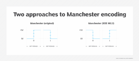
There are two approaches in Manchester encoding for interpreting the voltage transitions. The first is based on the original Manchester encoding process developed in the late 1940s. The second approach is defined by the Institute of Electrical and Electronics Engineers in its publication IEEE 802.3.
The original approach is based on the work of G.E. Thomas and other engineers at the University of Manchester in Manchester, England. In this system, the transition from low voltage to high voltage represents logic 0, and the transition from high to low represents logic 1. In IEEE 802.3, the opposite is true -- the transition from low to high represents logic 1, and the transition from high to low represents logic 0.
Figure 1 shows the two approaches to Manchester encoding. The horizontal blue lines represent the voltage level. In this case, +5V is used for the high level and 0V for the low level. The vertical blue lines represent that transition from one level to the other, with arrows indicating the direction of the transition. In both cases, the transition occurs at the middle of the bit period, with the bit state determined by the direction.
More approaches to data encoding
Other approaches to data encoding are based on the voltage level rather than on the transition from one level to the other. For example, non-return-to-zero (NRZ) encoding often uses the higher voltage to represent 1 and the lower voltage to represent 0. Figure 2 shows an NRZ signal for the bits 10010110, along with the clock signal, which is synchronized with the NRZ bitstream to ensure each bit is properly communicated.
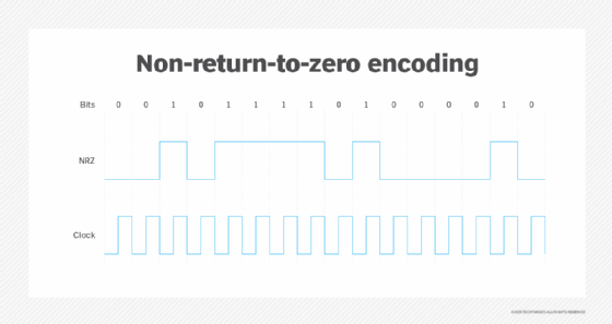
The clock signal has a constant frequency and, ideally, remains continuously synchronized with the data signal. There are various ways to achieve this, but one of the most common is to transmit the clock signal on a separate line, in conjunction with the data line. Unfortunately, the separation of the two signals raises the risk of bit encoding errors because the signals can become out of sync. If the bitstream contains long sequences of consecutive 1's or 0's, bits might be dropped or extra bits added with the slightest disruption to one of the signals.
Because Manchester encoding combines the clock and data signals into a single bitstream, these types of errors are less likely to occur. The signal synchronizes itself, which minimizes the error rate and provides a more reliable mechanism for transmitting data. Figure 3 shows the Manchester encoding for bits 10010110, using both the original standard and the IEEE 802.3 standard. The clock signal is shown separately to demonstrate how it syncs with the data bitstreams and the transitions between voltage levels, although it is encoded within the Manchester bitstreams.
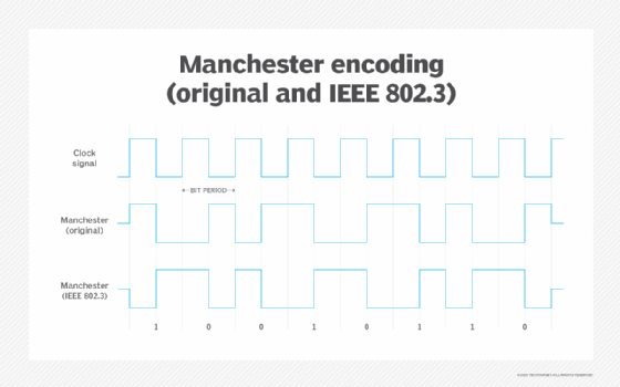
Manchester encoding uses an exclusive OR (XOR) Boolean function to combine the clock and data signals into a single bitstream. Each bit period reflects the transition from one voltage level to another. The transition always occurs at the bit period's midpoint, providing a clear indication of the bit state. This is true whether working with the original Manchester standard or the IEEE 802.3 standard.
The main disadvantage of Manchester encoding is that it requires more bits to be transmitted than a bitstream that doesn't include the clock signal, making it less suited to situations where bandwidth is an issue. Manchester encoding might also introduce frequency-related issues at higher data rates, further limiting its potential use.
In the right circumstances, however, Manchester encoding can be a valuable asset, particularly when reliability is crucial or when a separate clock signal is not practical. For this reason, Manchester encoding is commonly used in radio frequency identification, near-field communication and infrared protocols.