What is the data link layer in the OSI model?
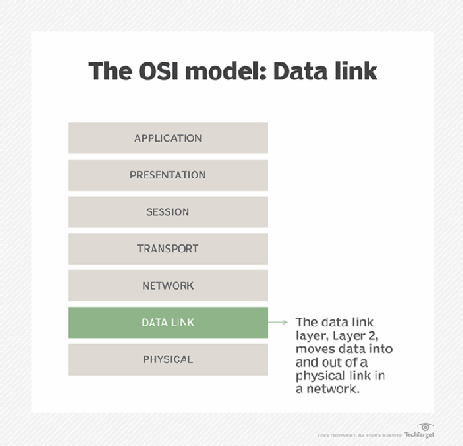
The data link layer is the protocol layer in a program that handles how data moves in and out of a physical link in a network. It is Layer 2 in the Open Systems Interconnection (OSI) architecture model, and its main purposes are to facilitate data transfers between network entities and to ensure reliable error-free transmission.
Functions of the data link layer
The data link layer has four main functions:
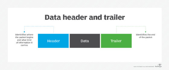
- Framing. The data link layer divides each datagram into frames, each with its own unique header and trailer to enable smooth communication between senders and receivers over the network.
- Flow control. This layer, flow control, ensures data flows at a pace that doesn't overwhelm the devices that send and receive data.
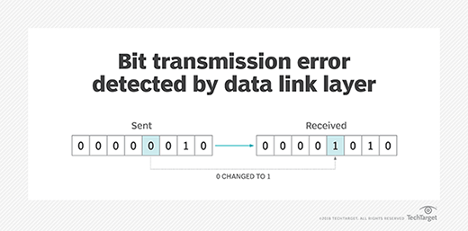
- Error detection and correction. This layer troubleshoots problems that occur as a result of bit transmission errors.
- Reliable data delivery. The data link layer permits the transmission of data to Layer 3, the network layer, where it can be addressed and routed.
Multiple devices operate at the data link layer to carry out the above functions. A switch connects these devices on a local area network (LAN) by forwarding data frames to the correct receiver device using media access control (MAC) addresses. Similarly, a network interface card adds MAC addresses to the frames and sends them over the physical medium. Wireless access points also work on the data link layer to manage wireless MAC addresses and to enable wireless devices to connect to a wired network.
What is the data link layer responsible for?
The OSI model of computer networking is a conceptual rather than a physical model. Its seven-layer framework provides a method for visualizing computer networking and data flow in a network. It also provides a standardized language with specific rules and protocols that enable diverse networking technologies and entities to effectively communicate with each other.
The data link layer and its various protocols play an important role in facilitating data transmissions in the following:
- Point-to-point links.
- LANs.
- Wireless networks.
The data link layer lies just below Layer 1 of the OSI model, which is the physical layer. When the physical layer already exists, the data link layer encodes, decodes and organizes data bits -- also known as data frames -- and then transports them as frames between two adjacent nodes on the same LAN or wide area network. It thus controls the flow of data, as well as access to the transmission medium.
Additionally, the data link layer determines how devices recover from collisions that might occur when multiple nodes on the network attempt to send frames at the same time. In other words, it provides a way to detect and correct errors in the physical layer, thus facilitating largely error-free data transmissions.
Framing in the data link layer
In the data link layer, framing refers to the encapsulation of data to be sent over a network into multiple frames. Upon receiving a packet of information, the data link layer divides it into a sequence of bits known as a frame. These frames cannot cross a local network's boundaries. This enables the layer to focus on local packet addressing and delivery.
Each frame has its own header and trailer, as well as a specific syntax or structure. This enables the data receiver to identify where the frame starts and ends. The header and trailer also enable receivers to distinguish between different frames.
Framing is also important for facilitating error detection. The receiver detects bad blocks of data encapsulated in frames and then either corrects or discards those frames.
The "framing problem" is a common issue in the data link layer. It refers to the challenge of correctly identifying the start and end of data frames within a continuous stream of bits so the receiver can efficiently extract those frames for error-free communication. One way to avoid this problem is to ensure that the physical layer remains idle for some time after it transmits a frame. The receiver detects the idle period and can, therefore, better identify frame boundaries, thus preventing errors and collisions. However, this approach might not always be feasible, particularly in situations that require high speeds and idle time for communications is unacceptable.
Sublayers of the data link layer
The data link layer has two sublayers: the logical link control (LLC) sublayer and the MAC sublayer.
The multiplexing, flow and synchronization capabilities of the data link layer come from the LLC sublayer. According to the IEEE 802 LAN specification, the LLC sublayer, which is the upper sublayer of the data link layer, controls data flow among various applications and services. By interfacing between the data link layer and the next layer in the OSI model -- the network layer -- and by providing acknowledgement and error notification mechanisms, it ensures smooth data communications. The LLC sublayer can talk to a number of IEEE 802 MAC sublayers, which control access to the physical media for transport. It is also responsible for the physical addressing of frames and for facilitating multipoint communications.
The data link layer requires MAC addresses to handle a packet's journey across a local network and to correct any transmission errors that might occur along the way. Each device on the network has a unique 12-digit MAC address that locates devices and enables them to communicate with each other. The data link layer, specifically the MAC sublayer, reserves a unique MAC address for every station on the network and uses these addresses to establish a communication channel on that network. It encapsulates frames so they can be transmitted over the network and resolves addressing issues in the source and destination stations. It also resolves network collisions -- a situation where multiple packets attempt to use the same channel at the same time -- and initiates packet retransmissions in case a collision does occur.
Ethernet and 802.11 wireless specifications are the most common MAC layer types. Ethernet offers two types of MAC sublayers: half-duplex and full-duplex. In half-duplex Ethernet -- the original mode of Ethernet operations -- only one station or node on the network can transmit at any given time, meaning other nodes must wait for that node to finish transmitting before they can start their own transmission. If they don't wait, a collision occurs, resulting in transmission errors and possible data losses. In full-duplex Ethernet, multiple stations can transmit at the same time, enabling simultaneous communication between them.
Here's how the two sublayers of the data link layer enable data transmission:
- The LLC sublayer delivers data to the MAC sublayer.
- The MAC sublayer adds the source and destination MAC addresses to the data.
- It stores the data in a buffer.
- It also forms an Ethernet frame and sends it to the destination node after checking its MAC address.
- The destination node checks the MAC address table to confirm the destination MAC address is present. If it finds a matching entry, it accepts the frame. Otherwise, it discards the frame.
This is the process for data transmission in unicast mode -- i.e., when a frame is sent from a single transmitting device to a single destination device using a MAC address. In multicast mode, multicast group Internet Protocol addresses are assigned to devices and added to the MAC address table. The LLC then delivers frames with the multicast MAC address to the MAC sublayer. This sublayer then transmits the frames to the upper layer.
Data link layer and error detection
Error detection and correction are key functions of the data link layer. The layer ensures an initial connection has been set up, divides output data into data frames and handles the acknowledgements from a receiver that confirms whether data has successfully arrived. It also analyzes bit patterns at specific places in the frames, which ensures incoming data has been successfully received.
If an error occurs, the data link layer notifies higher-level protocols that something has happened to the physical link. Frame sequencing capabilities within the data link layer permit the receiving device to reorder frames that might have been transmitted out of sequence. The data link layer verifies the packet isn't impaired.
The data link layer also manages flows by enabling devices on a link to detect congestion. Nearby devices then transmit congestion information so traffic can accordingly reroute on the network.
Data link layer protocols
Numerous protocols are associated with the data link layer. These protocols specify how devices send and receive data frames on the network and how they might detect and recover from collisions. Some protocols also provide standardized methods to prevent or reduce collisions.
The following are some examples of data link protocols:
- Synchronous Data Link Control (SDLC). A bit-oriented, synchronous protocol, SDLC uses frames with a specific structure and a flow control mechanism to facilitate reliable communications between data senders and receivers.
- High-Level Data Link Control (HDLC). HDLC is a bit-oriented internet protocol based on SDLC and used for point-to-point and multipoint communications.
- Serial Line Internet Protocol (SLIP). This method adds framing bytes at the end of an IP packet to facilitate communication over serial ports and internet service provider modems.
- Point-to-Point Protocol (PPP). PPP is a character-oriented protocol with an error detection function to reliably transport IP and other packets over serial lines.
- Link Access Procedure (LAP). LAP is a family of protocols to frame and reliably transfer data over point-to-point links.
- Network Control Protocol (NCP). NCP is an older data link protocol that enables access and file transfers between distant devices.
- Link Control Protocol (LCP). LCP is a protocol to establish, configure, test and terminate a data link connection to transmit data frames and to negotiate for maximum packet lengths.
Networking enables the internet to function, relying on several key protocols. These commonly used network protocols facilitate communication and connections across the internet. Learn about the common network protocols and their functions.