What is an entity relationship diagram (ERD)?
An entity relationship diagram (ERD), also known as an entity relationship model, is a graphical representation that depicts relationships among people, objects, places, concepts or events in an information technology (IT) system. An ERD uses data modeling techniques that can help define business processes and serve as the foundation for a relational database.
Importance of entity relationship diagrams
ERDs provide a visual starting point for database design that can also be used to help determine information system requirements throughout an organization. After a relational database is rolled out, an ERD can still serve as a reference point, should any debugging or business process reengineering be needed later.
While an ERD can be useful for organizing data that can be represented by a relational structure, it can't sufficiently represent semistructured or unstructured data. It's also unlikely to be helpful on its own in integrating data into a preexisting information system.
Key entity relationship diagram use cases
Applications or use cases describe how a person or entity interacts with a system or product to achieve a specific goal. They depict how a system will be used functionally in real-world situations. The following are some examples:
- Airport check-in. Describes the process of a passenger checking in online, selecting/confirming a seat and printing a boarding pass.
- Banking and finance. This is an example where customers check their account balances, transfer funds or pay bills.
- Business process re-engineering. These are essential when analyzing databases for business process re-engineering initiatives.
- Database design. These are important tools for modeling and designing relational databases.
- Database troubleshooting. Data from database ERDs can be used to analyze existing databases for problems.
- Education. ERDs are used for creating relational databases used for storing relational information for educational purposes.
- Flight reservation system. These are important as they define the various steps in the reservation process, such as viewing flight schedules, choosing a flight, adding services such as an executive lounge and making payment.
- Prescription medication system. Many different medication-related activities can be defined using ERDs, such as a doctor prescribing medication, a patient requesting a prescription refill and a pharmacy delivering the medication.
- Creating a shopping wish list. This is for customers who want to browse products online and then create and manage a wish list.
- Research. ERDs are used to set up databases that can be used to analyze structured data.
- Restaurant interactions. These can include reviewing a menu, initiating an order, setting delivery instructions and making payment.
How to create an entity relationship diagram
ERDs are generally depicted in one or more of the following models:
- A conceptual data model, which lacks specific detail but provides an overview of the scope of the project and how data sets relate to one another.
- A logical data model, which is more detailed than a conceptual data model, illustrating specific attributes and relationships among data points. While a conceptual data model does not need to be designed before a logical data model, a physical data model is based on a logical data model.
- A physical data model, which provides the blueprint for a physical manifestation -- such as a relational database -- of the logical data model. One or more physical data models can be developed based on a logical data model.
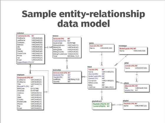
There are five basic components of an entity relationship diagram. Similar components will be designated by the same shape. For example, all entity types might be enclosed in a rectangle, while all attributes are enclosed in a diamond.
The components include the following:
- Entities, which are objects or concepts that can have data stored about them. Entities refer to tables used in databases.
- Attributes, which are properties or characteristics of entities. An ERD attribute can be denoted as a primary key, which identifies a unique attribute, or a foreign key, which can be assigned to multiple attributes.
- The relationships between and among those entities.
- Actions, which describe how entities share information in the database.
- Connecting lines.
Consider an ERD showing relationships between sales reps, customers and product orders. As shown in the diagram below, an ERD representing the information system for a company's sales department might start with graphical representations of entities such as the sales representative, the customer, the customer's address, the customer's order, the product and the warehouse. Then lines or other symbols can be used to represent the relationship between entities, and text can be used to label the relationships.
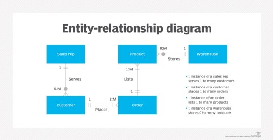
A cardinality notation can then define the attributes of the relationship between the entities. Cardinalities can denote that an entity is optional (for example, a sales rep could have no customers or many) or mandatory (at least one product must be listed in an order).
These are the three main cardinalities:
- A one-to-one relationship (1-1). For example, if each customer in a database is associated with one mailing address.
- A one-to-many relationship (1-M). For example, a single customer might place an order for multiple products. The customer is associated with multiple entities, but all those entities have a single connection back to the same customer.
- A many-to-many relationship (M-N). For example, at a company where all call center agents work with multiple customers, each agent is associated with multiple customers, and multiple customers might also be associated with multiple agents.
While there are tools to help draw entity relationship diagrams, such as computer-aided software engineering tools, some relational database management systems also have design capabilities built in.
Advanced components and notations in ERDs
Beyond traditional database design, ERDs are increasingly applied in designing NoSQL databases, service architectures, and identifying microservices and their interactions.
This broader utility of ERDs in capturing the relationships and data flows in complex IT systems lies in facilitating a more structured approach to developing scalable, maintainable systems.
While basic ERDs focus on entities, attributes, relationships, actions and connecting lines, the advanced modeling used in some applications requires a deeper dive into more complex components and notations:
- Weak entities are dependent on another entity (the owner) and cannot exist without it.
- Derived attributes represent values calculated from other attributes in the database.
- Reflexive relationships occur when an entity relates to itself, facilitating the modeling of complex hierarchical structures.
These advanced components, along with various notation systems, such as Crow's Foot, Chen's, or IDEF1X, empower advanced modelers to create more precise, detailed data representations.
Resolving the challenges of ERDs
While ERDs excel in modeling structured data, they face limitations with semistructured or unstructured data. To address these challenges, modern database systems and data modeling practices often complement ERDs with other models, such as JSON or XML schemas for semistructured data, or leverage NoSQL databases that inherently support unstructured data.
This holistic approach ensures that all data types in an information system are effectively represented and managed.
Additionally, with regulations like the General Data Protection Regulation (GDPR) and the California Consumer Privacy Act (CCPA) making data privacy and security paramount, ERDs play a crucial role in planning for data protection measures. By mapping out where sensitive data is stored and how it flows through the system, ERDs help identify potential vulnerabilities and ensure that appropriate security controls are in the right places.
Modern data modeling tools and ERD practices
ERDs remain a fundamental tool in data modeling. The relevance and application of ERDs have evolved, integrating seamlessly into Agile and DevOps methodologies, enhancing communication among cross-functional teams, and adapting to the nuances of both structured and unstructured data environments.
ERD integration into Agile and DevOps approaches facilitates a shared understanding of the database structure, ensuring all stakeholders are aligned on the data relationships and flows early in the development process. This collaborative use of ERDs promotes iterative refinement of the data model, allowing for rapid adjustments to address changing requirements and feedback.
The landscape of ERD tools has also expanded, with modern solutions like Lucidchart, Microsoft Visio and dbForge Studio offering advanced features for data modeling. These tools surpass traditional options by providing intuitive drag-and-drop interfaces, real-time collaboration capabilities and extensive template libraries.
Choosing the right tool and modeling strategy often depends on specific project requirements, including collaboration needs, data model complexity and integration needs.
Best practices and pitfalls in creating ERDs
Even if some of the more advanced techniques are not being attempted, it can be challenging to create an effective ERD that serves a business. Follow these best practices in preparing an ERD:
- Start with a clear definition of entities and their relationships.
- Use consistent notation to avoid confusion.
- Prioritize readability by arranging entities and relationships logically.
- Involve stakeholders in the modeling process to ensure the ERD meets business requirements.
- Avoid overcomplicating the diagram with unnecessary details.
- Update the ERD as the system evolves.
With the modern applications and tools available, ERDs built with best practices in mind continue to be invaluable assets in the development and maintenance of information systems; they support the visualization, planning, and communication of data relationships and structures.