What is a VPN (Virtual Private Network)? Definition, Benefits & How It Works

What is a VPN?
A VPN (virtual private network) is a service that creates a secure, encrypted connection between a user's device and a remote server, allowing private and anonymous internet browsing. VPNs protect data from hackers, mask IP addresses, and are commonly used for secure remote access and bypassing geographic restrictions.
Typically, a VPN is used over a less secure network, such as the public internet. Internet service providers (ISPs) normally have a rather large amount of insight into a customer's activities. In addition, some unsecured Wi-Fi access points might be a convenient avenue for attackers to gain access to a user's personal data. An internet user could use a VPN to avoid these encroachments on privacy.
VPNs can hide a user's browser history, Internet Protocol address (IP address) geographic location, web activity and devices. Anyone on the same network can't see what a VPN user is doing. This makes VPNs a go-to tool for online privacy. However, VPNs don't provide total anonymity, as ISPs can still see the size of incoming and outgoing traffic, but not the content.
VPNs use tunneling protocols to encrypt data at the sending end and decrypt it at the receiving end. Originating and receiving network addresses are also encrypted for better online security.
VPN apps are often used to protect data transmissions on mobile devices or to visit websites restricted by location. Don't confuse secure access through a mobile VPN with private browsing, however. Private browsing does not involve encryption; it is simply an optional browser setting that prevents identifiable user data from collection.
How do VPNs work?
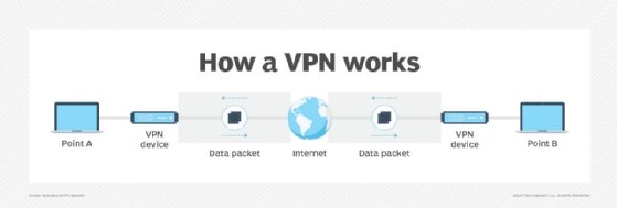
At its most basic level, VPN tunneling creates a point-to-point connection inaccessible to unauthorized users. To create the tunnel, VPNs use a tunneling protocol over existing networks. Different VPNs use different tunneling protocols, such as OpenVPN or Secure Socket Tunneling Protocol (SSTP). The tunneling protocol provides data encryption at varying strengths depending on the platform using the VPN, such as Windows operating system (OS) using SSTP. The endpoint device must run a VPN client (software application) locally or in the cloud. The client runs in the background and isn't noticeable to end users unless it creates performance issues.
VPNs associate a user's search history with the VPN server's IP address. VPN services have servers located in different geographic areas. By using a VPN tunnel, a user's device connects to another network. This hides its IP address and encrypts the data, shielding private information from attackers or others hoping to gain access to an individual's activities. The tunnel connects a user's device to an exit node in another distant location, which makes it seem like the user is from that location.
VPNs can affect performance in many ways, such as internet connection speed, protocol types a VPN provider can use and the type of encryption used. In enterprises, poor quality of service (QoS) outside the control of IT departments can affect performance.
A kill switch is a last-resort security feature in some VPN products. If anything disrupts the VPN connection, the kill switch automatically disconnects the device from the internet, eliminating the chance of IP address exposure.
There are two types of kill switches: application level and system level. Application-level kill switches shut down specific apps, while system-level kill switches shut off internet traffic if the VPN connection stops. Kill switches use the two following protocols:
- Active kill switch protocols. These prevent devices from connecting to unsafe networks when connected to the VPN. Apart from server disruptions, devices are disabled when not connected to the VPN.
- Passive kill switch protocols. These are more secure. They keep the device from connecting to non-VPN connections even while disconnected from the VPN server.
What are VPNs used for?
Regular internet users and organizations use VPNs for virtual privacy. Organizations deploy VPNs to ensure authorized users can access their data center using encrypted channels. VPNs also enable users to connect to a database from the same organization located in a different area.
VPNs provide remote employees, gig economy freelance workers and business travelers with access to software applications hosted on proprietary networks. To gain access to a restricted resource through a VPN, the user must be authorized to use the VPN and provide one or more authentication factors. These can be passwords, security tokens or biometric data.
When an internet user surfs the web, an attacker could access information, including browsing habits or IP addresses. If privacy is a concern, a VPN can provide users with peace of mind. Most users find value in VPN's encryption, anonymity and ability to get around geographically blocked content.
For example, getting around blocked content from another country might be extremely useful for journalists. If a country is likely to block internet content from foreign entities, journalists could use a VPN to look like they're within that country.
VPN protocols
VPN protocols ensure an appropriate level of security to connected systems when the underlying network infrastructure alone can't provide it. Several different protocols can secure and encrypt data. They include the following:
Benefits and challenges of using a VPN
Benefits of using a VPN include the following:
- The ability to hide a user's IP address and browsing history.
- Secure connections with encrypted data.
- Bypassing geo-blocked content.
- Making it more difficult for advertisers to target ads to individuals.
The challenges of using a VPN include the following:
- Not all devices support a VPN.
- VPNs do not protect against every threat.
- Paid VPNs are more trusted, secure options.
- A VPN might slow down internet speeds.
- Anonymity through VPNs has limitations -- for example, browser fingerprinting is still possible.
VPN security
Any device that accesses an isolated network through a VPN presents a risk of bringing malware to that network environment -- unless there's a VPN connection process requirement to assess the state of the connecting device. Without an inspection to determine whether the connecting device complies with an organization's security policies, attackers with stolen credentials can access network resources, including switches and routers.
Beyond VPNs, security experts recommend network administrators consider adding software-defined perimeter (SDP) components to their VPN protection infrastructure to reduce potential attack surfaces. The addition of SDP programming enables midsize and large organizations to use a zero-trust model for both on-premises and cloud network environment access.
Types of VPNs
Network administrators have several options when it comes to deploying a VPN that include the following.
Remote access VPN
Remote access clients connect to a VPN gateway server on the organization's network. The gateway requires the device to authenticate its identity before granting access to internal network resources. This type usually relies on either IPsec or SSL to secure the connection.
Site-to-site VPN
A site-to-site VPN uses a gateway device to connect an entire network in one location to a network in another location. End-node devices in the remote location do not need VPN clients because the gateway handles the connection. Most site-to-site VPNs connecting over the internet use IPsec. It is also common for them to use carrier Multiprotocol Label Switching (MPLS) connections rather than the public internet as the transport. It is possible to have either Layer 3 connectivity (MPLS IP VPN) or Layer 2 (virtual private local area network service) running across the base transport links.
Mobile VPN
In a mobile VPN, the server still sits at the edge of the organization's network, enabling secure tunneled access by authenticated, authorized clients. Mobile VPN tunnels are not tied to physical IP addresses, however. Instead, each tunnel is bound to a logical IP address. That logical IP address stays bound to the mobile device. An effective mobile VPN provides continuous service to users and can switch across access technologies and multiple public and private networks.
Hardware VPN
Hardware VPNs offer a number of advantages over software-based VPNs. In addition to offering enhanced security, hardware VPNs can provide load balancing for large client loads. Web browser interfaces manage administration. A hardware VPN is more expensive than a software-based one. Because of the cost, hardware VPNs are more viable for larger businesses. Several vendors offer devices that can function as hardware VPNs.
Cloud VPN
Cloud VPNs provide users with a secure internet connection via the cloud. This is beneficial for organizations with cloud-based network infrastructure or distributed and remote workforces. With a cloud VPN, users can access corporate networks remotely regardless of location.
VPN appliance
A VPN appliance, also known as a VPN gateway appliance or SSL VPN appliance, is a network device with enhanced security features. It is a router that provides protection, authorization, authentication and encryption for VPNs.
Dynamic multipoint virtual private network (DMVPN)
A DMVPN exchanges data between sites without needing to pass through an organization's headquarters VPN server or router. A DMVPN creates a mesh VPN service that runs on VPN routers and firewall concentrators. Each remote site has a router configured to connect to the company's headquarters device (hub), providing access to the resources available. When two spokes are required to exchange data between each other -- for a voice over IP telephone call, for example -- the spoke contacts the hub, obtains the needed information about the other end and creates a dynamic IPsec VPN tunnel directly between them.
VPN vendors and products
VPN services are available as free or paid options. Paid vendor options are more often recommended than free ones, however. Some VPN vendors include the following:
- NordVPN contains a strong collection of security features with a large server collection. NordVPN has features such as Tor browser connections for anonymous web surfing while maintaining a strong stance on customer privacy.
- Private Internet Access VPN is an app for most OSes. It can support an unlimited number of device connections, including phones, PCs and smart TVs. It does not offer many advanced features and privacy tools, but it is still considered a good VPN service.
- ExpressVPN is a VPN service with a large and diverse set of distributed servers. It has strong privacy and information practices focused on security. It offers extra features such as split tunneling and uses the OpenVPN protocol.
How to choose a VPN
VPNs are legal in the U.S., but users and organizations should check if they are legal in other countries.
Many VPNs offer extremely similar technologies, so it can be hard to choose which VPN will work best. Paid VPN services tend to be more trusted and include more security features. Reputable VPN services are upfront about their security, strengths and weaknesses, and transparency by releasing third-party audits. Extra VPN features include split tunneling, access to the Tor network or multihop connections.
Once individuals look at the added features and find a service they think will work for them, it's a good idea to start out with a short-term subscription. Many vendors offer free trials of their paid versions. Some free trial versions might include a limit on data use.
History of VPNs
VPN technology was first used in 1996 when a Microsoft employee developed PPTP. The protocol created a more secure private connection between a user device and the internet. In 1999, Microsoft published the specification.
In the early 2000s, VPNs were mostly associated with and used by businesses to access private business networks. In this use case, organizations were able to access company data from anywhere while looking as if they were in the office. Secure file sharing between different offices became possible. However, the technology wasn't often used by average online users.
After this, encryption standards became more powerful and new tunneling protocols were developed. As individuals started to learn about potential online threats and privacy issues, VPN use expanded to individual, at-home users. Privacy scandals were injected into the modern zeitgeist, such as WikiLeaks or the separate security leaks by Edward Snowden.
Around 2017, internet users in the U.S. learned that ISPs could collect and sell their browsing history. Net neutrality became a concept citizens had to fight for -- and effectively lost. The U.S. House of Representatives passed a bill in 2019 to bring back net neutrality but was ultimately blocked by the Senate. In 2024, the FCC voted to restore net neutrality, but U.S. courts blocked the ruling in August of the same year. Some states have enacted versions of net neutrality laws. With this knowledge, the use of VPNs became a more legitimate need for individuals.
Editor's note: This definition was updated to reflect industry changes and improve the reader experience.
Alexander Gillis is a technical writer for the WhatIs team at TechTarget.