What is a router?
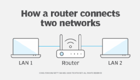
A router is a physical or virtual appliance that passes information between two or more packet-switched computer networks. These networks can be local area networks (LANs), wide area networks (WANs) or a combination of the two. A router inspects a given data packet's destination internet protocol (IP) address, calculates the best way to reach its destination and then forwards it accordingly.
A router is a common type of gateway. It's positioned where two or more networks meet at each point of presence on the internet. Hundreds of routers might forward a single IP packet as it moves from one network to the next on the way to its final destination. Routers exist on Layer 3, the network layer, of the Open Systems Interconnection model.
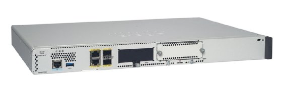
Traditional routers are standalone devices that use proprietary software. A virtual router is a software instance that performs the same functions as a physical router. Virtual routers typically run on commodity servers, either alone or packaged with other virtual network functions, such as firewall packet filtering, load balancing and WAN optimization capabilities.
Other network devices, such as wireless access points and network switches, might include built-in router functionality.
Why use a router?
A router sends data packets to their correct destinations and enables multiple devices to share the same internet connection. It acts as a central hub, receiving internet traffic and distributing it to the correct devices on the local network. It lets those devices share the same public IP address and connection.
Routers also let connected devices communicate without needing internet access, facilitating the creation of local network.
How a router works
When a network device such as a laptop or a phone sends data to another device, that data is broken down into packets. Each packet's header contains important information, such as the source and destination IP address. A router examines a packet header's destination IP address and compares it with a routing table to determine the packet's best next hop.
Routing tables list directions for forwarding data to network destinations, sometimes in the context of other variables, such as cost. They amount to an algorithmic set of rules that calculate the best way to transmit traffic toward any given IP address.
A routing table often specifies a default route, which the router uses whenever it fails to find a better forwarding option for a given packet. For example, a typical home office router directs all outbound traffic along a single default route to its internet service provider (ISP).
Routing tables are either static or dynamic. Static routers are manually configured, while dynamic routers automatically update their routing tables based on network activity and exchange information with other devices using routing protocols.
Many routers also perform Network Address Translation (NAT), which shields the private IP addresses of a LAN by readdressing all outgoing traffic with a single shared public IP address. NAT helps to conserve globally valid IP addresses and improve network security.
The difference between a router and a modem
The terms modem and router are sometimes used interchangeably when describing a home network, but they're not the same.
Modems
A modem connects a home or office to the ISP and converts the analog internet signal into a digital format that devices understand. It connects directly to the ISP, providing an internet connection, but doesn't create a local network. Typically, modems don't have built-in wireless capabilities and offer only a wired internet connection.
Routers
In contrast, a router takes the internet connection from the modem and distributes it to various devices within a home or office network. This enables devices to connect either wirelessly or through Ethernet cables.
The router creates a LAN, enabling multiple devices to connect, communicate with each other and access the internet. Routers come with wireless or Wi-Fi capabilities, enabling devices to connect to the network without needing Ethernet cables.
It's common today to have a single device that combines both modem and router functions. These devices are often referred to as modem routers or gateways.
Types of routers
Some of the different types of network routers include the following:
- Wired routers. These routers physically connect devices to the internet using Ethernet cables. Wired connections provide higher internet speeds and are generally more reliable and secure than wireless ones. They're ideal for environments, such as data centers, where a stable and high-speed connection is essential.
- Wireless routers. A wireless router works in the same way as the router in a hard-wired home or business LAN but enables greater mobility for notebook or portable computers. Wireless routers use the 802.11g specification, a standard that offers transmission over short distances.
- Core routers. ISPs use core routers, the fastest and most powerful types of routers. Core routers provide maximum bandwidth for connecting additional routers or switches. They sit at the center of the internet and forward information along the main fiber optic backbone. Enterprise routers connect large organizations' networks to core routers.
- Edge routers. An edge router, also known as an access router, is a lower-capacity device that resides at the boundary of a LAN and connects it to the public internet, a private WAN or an external LAN. Subscriber edge routers are edge routers used in home and small office routers.
- Branch routers. These routers link an organization's remote office locations to its WAN, connecting to the primary campus network's edge routers. They often provide additional features, such as time-division multiplexing, wireless LAN management capabilities and WAN application acceleration.
- Virtual routers. A virtual router is a software-based emulation of a physical router. It divides one physical router into multiple isolated units, enabling the device to operate as several independent routers. Each virtual router has its own routing tables, interfaces and configurations. Virtual routers are typically used to create separate routing instances for different virtual private networks on the same device or in multi-tenancy environments, where customer traffic must be isolated within a shared infrastructure.
- Logical routers. A logical router is a configured partition of a traditional network hardware, or physical router. It's viewed as an enhanced virtual router with dedicated hardware resources, such as a specific central processing unit, memory and network interfaces assigned to each logical router instance. Logical routers replicate the hardware's functionality, creating multiple routing domains within a single router. They perform a subset of the tasks that physical routers can complete, and each logical router can contain multiple routing instances and routing tables.
Routing protocol categories
Routing protocols determine how a router identifies other routers on the network, keeps track of all possible destinations and makes dynamic decisions about where to send each network message. Routing protocols are typically categorized into the following three types:
Distance vector and link-state protocols
Distance vector protocols use the distance to determine the best route to a destination, which is usually measured in hops. Each router shares its routing table with its immediate neighbors, aiding in the calculation of the optimal path. Routing Information Protocol (RIP) is an example of a distance vector protocol.
Link-state protocols determine the best routing path to a destination while maintaining a complete view of the network topology. Each router shares information about its directly connected neighbors to create a map of the network. This enables routers to calculate the shortest path to each destination based on various metrics, such as cost or speed. Open shortest path first (OSPF) is an example of a link-state routing protocol.
Interior and exterior gateway protocols
Interior Gateway Protocols (IGPs) exchange routing information within a single autonomous system. Within an AS, routers use these protocols to identify the optimal path for data transmission. IGPs are typically employed for smaller-scale routing within an organization, often confined to a single building or a cluster of connected buildings. Common examples of IGP protocols include RIP, OSPF and Enhanced Interior Gateway Routing Protocol (EIGRP).
Exterior Gateway Protocols (EGPs) exchange routing information between different ASes. They are essential for routing across the broader internet, as they enable different networks to communicate and determine the best paths for traffic moving from one AS to another. The most commonly used EGP is the Border Gateway Protocol (BGP).
Hybrid protocols
Hybrid protocols integrate characteristics of both distance vector and link-state protocols to enhance efficiency and scalability. EIGRP is a notable example of a hybrid protocol. While it primarily follows distance vector principles, it also keeps a topology map similar to that of link-state protocols.
Examples of routing protocols
The various routing protocols currently in use include the following:
- Open Shortest Path First. OSPF finds the best path for packets as they pass through a set of connected networks. The Internet Engineering Task Force designates OSPF as one of several Interior Gateway Protocols.
- Exterior Gateway Protocol. While exterior gateway protocols are a category of protocols as mentioned above, there is also an older protocol named EGP. EGP determines how routing information exchanges between two neighbor gateway hosts that each have its own router. Hosts on the internet commonly use EGP to exchange routing table information. This protocol is obsolete now and has largely been replaced by BGP due to its lack of support for multipath networking environments.
- Border Gateway Protocol. BGP manages how packets are routed across the internet through the exchange of information between edge routers. BGP offers network stability that guarantees routers can quickly adapt to send packets on an alternate internet path if the one they're using goes down.
- Interior Gateway Routing Protocol. IGRP determines how an autonomous network exchanges routing information between gateways. Other network protocols then use the routing information to specify how transmissions should be routed. In 1993, EIGRP replaced IGRP due to the shift to classless IPv4 addressing, which IGRP was unable to support.
- Enhanced Interior Gateway Routing Protocol. EIGRP evolved from IGRP. If a router can't find a route to a destination in one of these tables, it queries nearby routers, which then query routers closer to them until a route is found. When a routing table entry changes in one of the routers, it notifies nearby routers of the change instead of sending the entire table.
- Routing Information Protocol. RIP is the original protocol that defines how routers should share information when traffic moves among an interconnected group of LANs. The largest number of hops allowed for RIP is 15, which limits the size of networks that RIP can support. RIP is rarely used in modern networks, except in very small networks.
Router security challenges
While routers play a crucial role in network connectivity, they also face numerous security challenges that threaten network integrity and safety. Here are some of the primary challenges:
- Firmware vulnerabilities. If a router's firmware or operating system is outdated, it could have known security vulnerabilities that hackers can exploit. Manufacturers frequently release updates to address these flaws, but users don't always install them in a timely manner. Additionally, attackers replace legitimate firmware with malicious versions that let them take control of the router, intercept traffic or steal sensitive data.
- Weak or default credentials. Many routers come with default usernames and passwords that are easily found online. If these credentials aren't changed, anyone could gain access to the router's settings. Even when users do change their passwords, they might still opt for weak passwords that can be easily guessed or cracked through brute-force attacks. The latest NIST password guidelines recommend permitting passwords up to 64 characters and advise a minimum of 8 characters for basic security.
- Denial-of-service attacks. DDoS attack is a common method of flooding a router with excessive traffic. This surge in data can exceed the router's processing capabilities, resulting in system crashes or severe latency. The router becomes unresponsive, leading to significant disruptions in network connectivity and preventing users from accessing essential online services.
- Router misconfigurations. Routers have ports that facilitate various types of network traffic. If these ports are left open when they aren't needed, attackers can use them as a potential entry point. Convenience features for routers can also introduce security risks. For example, Wi-Fi Protected Setup, designed to simplify Wi-Fi router connections by using a button or PIN, can be a vulnerability if not properly configured.
- Physical access. If someone gains physical access to a router, they could potentially reset it, change its settings or even install malicious software.
Learn the key differences between a router and a wireless access point. Discover how factors such as network size, organizational needs and user count help in choosing the correct device for a network.