serial peripheral interface (SPI)
What is a serial peripheral interface (SPI)?
A serial peripheral interface (SPI) is an interface commonly used in computers and embedded systems to facilitate short-distance communication between a microcontroller and one or more peripheral integrated circuits (ICs). Multiple transmission lines or signal wires connect the SPI chips, enabling the microcontroller to exchange data with the peripherals.
Motorola developed the SPI architecture in the 1980s to provide an interface that supports serial, synchronous and full-duplex communications:
- Serial. Data is transmitted over a single line one bit at a time in sequential order. This is in contrast to parallel communication, in which data is transmitted in parallel across multiple lines. Serial interfaces have simpler wiring, can support longer cables and are less prone to crosstalk between cable wires.
- Synchronous. Data is transmitted in a continuous data stream that works in conjunction with a timing signal used by both the transmitter and receiver. In contrast, asynchronous transmissions can be random or irregular and do not rely on a common clock. Synchronous communications are faster and come with less overheard than asynchronous communications.
- Full-duplex. Data can be transmitted in both directions at the same time. This is in contrast to half-duplex communications that support bidirectional communication but with only one node transmitting data at a time.
The SPI approach to data transmission is similar Microwire, an older interface from National Semiconductor. Both SPI and Microwire support serial and synchronous communications. However, Microwire is limited to half-duplex transmissions, while SPI can deliver full-duplex transmissions. Microwire chips are sometimes considered a subset of SPI chips.
An SPI controller can transmit data to and from many types of peripheral devices, including shift registers, memory chips, input/output expanders, SD memory cards, data converters, flash storage, multimedia cards, sensors and even other microcontrollers.
How does a serial peripheral interface work?
SPI components are commonly implemented in a 4-wire configuration. Each wire carries a specific type of signal between the controller and the peripherals. The naming conventions used to describe this configuration varies from one source to the next.
The original naming was based on the concept of a master-slave architecture in which the master controlled the slaves. The tech industry has been slowly moving away from this terminology in an effort to promote language that is more culturally sensitive. This effort has extended to SPI, which is often described as a master-slave interface. In this context, master is being replaced with controller, main or another term, and slave is being replaced with peripheral, subnode or a different label.
The Open Source Hardware Association (OSHWA) has been instrumental in the effort to revise SPI labeling. The organization recommends the industry use the following terms to describe the SPI signals in a 4-wire configuration:
- Serial clock (SCK). The clock signal that is generated by the controller to provide the timing signal necessary to keep the controller and peripheral in sync. The clock is also referred to as CLK, SCLK or other terms. Clock labeling has not changed with the new naming conventions.
- Peripheral out/controller in (POCI). The signal that carries the data from the peripheral to the controller. Until recently, this signal was commonly referred to as MISO (master in/slave out). In some instances, MISO refers to main in/subnode out.
- Chip select (CS). The signal determines which peripheral should be made active when the controller needs to communicate with one of multiple peripherals. At one time, the signal was commonly referred to as SS (slave select).
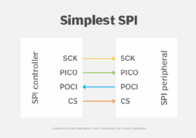
The simplest SPI configuration consists of one controller and one peripheral. The clock signal (SCK), outbound data signal (PICO) and chip selection signal transmit data from the controller to the peripheral, as shown in Figure 1. The inbound data signal (POCI) carries data from the peripheral to the controller. The inclusion of both the PICO and POCI signal wires makes it possible to support full-duplex communications.

The controller always initiates communication with the peripheral and always generates the clock signal. Data transmissions between the controller and peripheral are synced to the clock. One data bit is transferred in each clock cycle, so the faster the clock frequency, the greater the data transfer rate. Because the controller generates the clock, it controls the data flow.
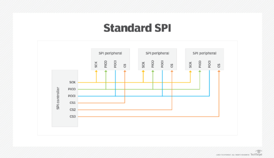
A single controller can communicate with multiple peripherals. Two basic approaches are used to support multi-peripheral configurations: standard and daisy-chain. In a standard configuration, the SCK, PICO and POCI signal lines are shared, but not the chip selection line. Instead, the controller provides an individual chip selection line for each peripheral, establishing a direct connection between the controller and the peripheral, as shown in Fig. 2.

When a peripheral is idle, the chip selection line is typically set to a high voltage level, in which case, the peripheral is enabled by setting its chip selection line to a low voltage level. Only one peripheral should be enabled at a time to avoid data contention on the shared signal lines.
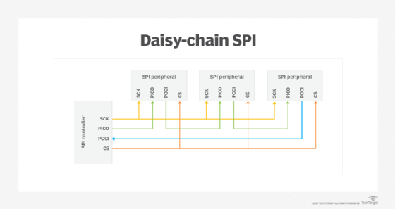
The daisy-chain configuration takes a different approach. The controller provides only one chip selection line, which is shared by all the peripherals. The data itself moves out from the controller from one peripheral to the next, cascading down the chain. Only the last peripheral returns data to the controller, as shown in Fig. 3.

A variation of the standard 4-wire configuration is the 3-wire approach. In this setup, the PICO and POCI lines are combined into one signal wire that supports bidirectional communications. OSHWA refers to this line as serial data in/out (SDIO). Because of the shared line, the 3-pin configuration supports only half-duplex communications, similar to Microwire.
Learn about the top secure data transmission methods and the difference between half-duplex and full-duplex communication.
TechTarget is responding to readers' concerns, as well as profound cultural changes, when it comes to certain commonly used but potentially linguistically biased terms. In some cases, we are defaulting to industry-standard terminology that may be seen as linguistically biased in instances where we have not found a replacement term. We are actively seeking out and giving preference to terms that properly convey meaning and intent without the potential to perpetuate negative stereotypes.
